Materials
and Design in the Roman Harbour of Soli-Pompeiopolis:
The
ROMACONS Field Campaign of August 2009
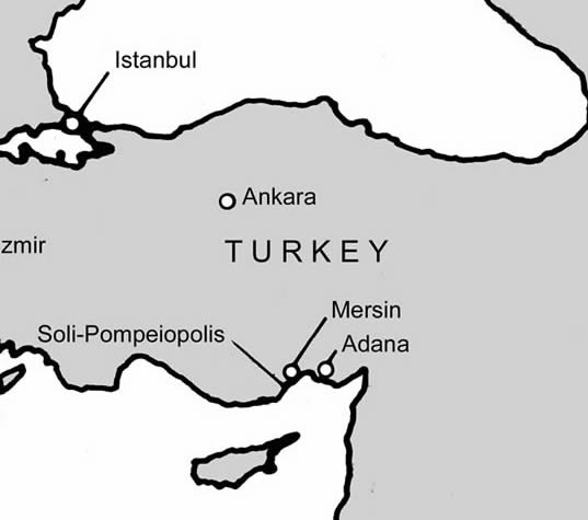
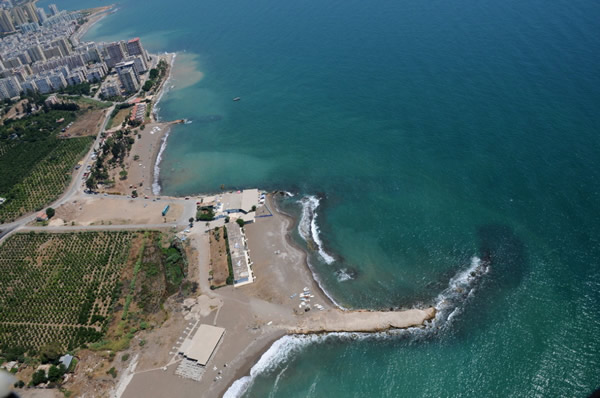
To the west
of Mersin, on the southeast Mediterranean coast of Turkey lie the ruins of
Soli/Pompeiopolis, now surrounded by the modern town of Mezitli (Figure 1). The
city has a long maritime history. Initially named
Soloi, the settlement was supposedly founded by Argives following the Trojan
wars and populated by Rhodians from Lindos some four centuries later.
Subsequently it was ravaged during the Mithradatic wars (89 – 81BC) and
eventually abandoned (Strabo 14.5.8). In 67 BC, Pompey the Great restored the
city and colonised it with survivors from his successful campaign against the
Cilician pirates who re-named it Pompeiopolis.
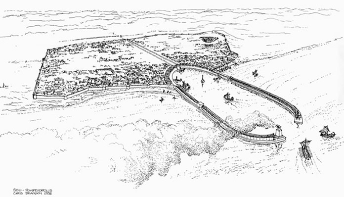
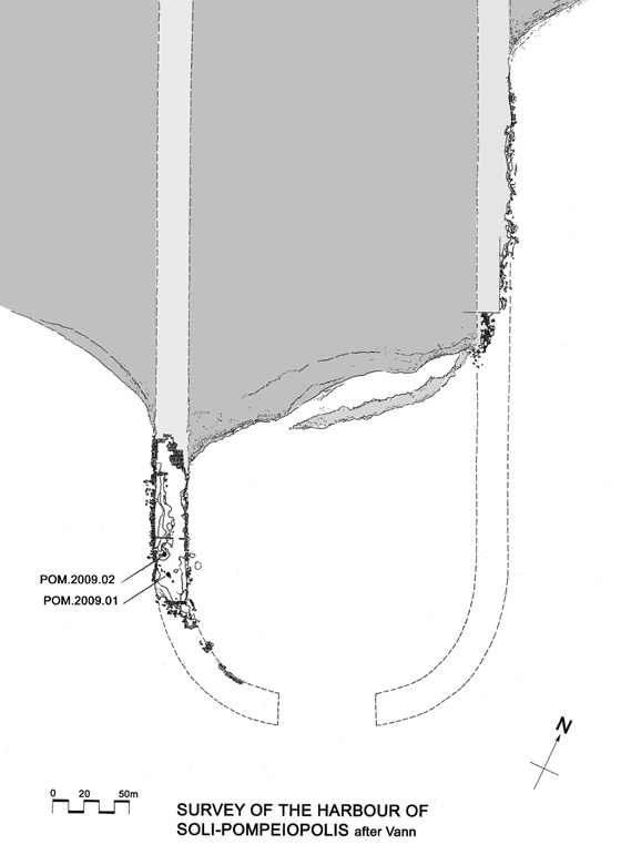
Since the harbour installations visible today date to the Roman period, we will subsequently refer to the site simply as Pompeiopolis. The portion of the harbour still well preserved presents an atypical example of Roman maritime engineering in which well clamped ashlar masonry encases a hydraulic concrete core. Although founded in part on a natural reef, it was largely an artificial harbour laid out to a symmetrical geometric design. The harbour was sheltered by two opposed, curving moles 320m long and approximately 23m wide, set 180m apart. They joined on the landward end in a semicircle. The seaward ends curved inwards to frame the harbour entrance (Figure 2).
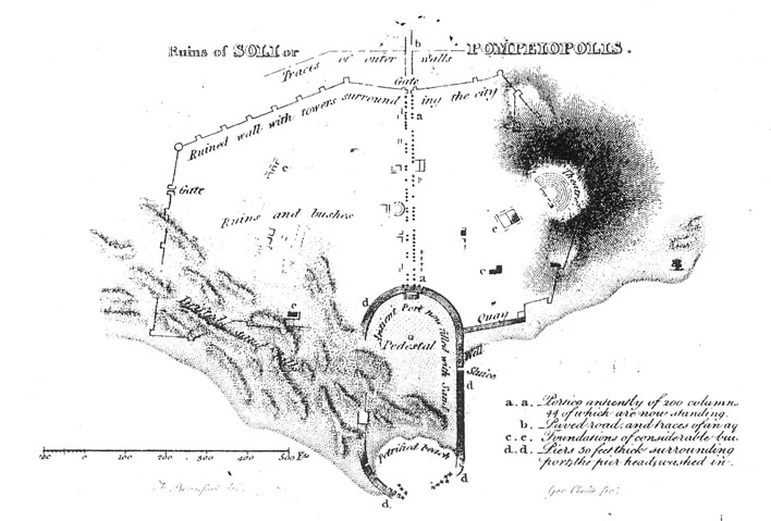
Most of the eastern mole has now disappeared, and the landward half of the moles is now surrounded or covered by silt and sand. The shape of the harbour was first illustrated in the modern era by Sir Francis Beaufort in his book, Karamania, published to accompany his survey of the southern coast of Turkey between 1811 and 1812 (Figure 3; Beaufort, 1817: 248-56).
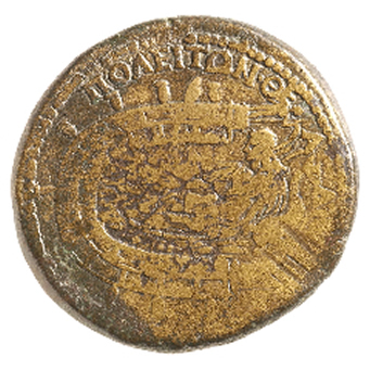
An ancient, stylised plan of the harbour also appears on a coin struck by Antoninus Pius between 143 and 145 AD (Figure 4)(Boyce, 1958: 67-78).
Although the harbour has continued to deteriorate and has in part been built over since it was recorded by Beaufort, it is still possible to make out its plan from aerial photographs, and a substantial section of the western jetty survives in surprisingly good condition (Figures 5, 6).
Beaufort’s plan shows what is called a “sluice” on the eastern mole near
the shoreline of that period. There is now no clear evidence for it, although
Vann suggests that a 3 m gap in the concrete near the present beach restaurant
could be part of it (Vann, 1995: 531). Ancient harbour engineers knew about the
need for flushing devices that would, if properly designed, allow water to flow
through the harbour basin and prevent it from silting up. How effective they
were is a matter of debate. A complicating factor is the possibility that the
Mezitli River (modern name) might once have run through the centre of the
ancient city alongside the colonnaded cardo and flowed into the
harbour with all its accompanying burden of silt. At some point well before
Beaufort’s visit the harbour was completely clogged with sand and fell out of
use. Beaufort’s plan shows it much as it is today, with over three quarters of
the basin landlocked and sand dunes covering most of the western side of the
harbour.
Although the
western mole is the best preserved of the two, only 160 m of the seaward leg is
now visible. The curved seaward head lies in ruins, scattered on the seabed,
while the landward length is buried under the sand and under the road skirting
the ancient basin. The surviving western section, standing in the sea, did so
because it was founded on a natural reef whilst the eastern arm was built on
sand. The absence of a firm foundation allowed its seaward length to collapse
and essentially disappear. The seabed in this area is now strewn with ashlar
blocks and rubble and there is no visible coherent structure.
Both moles were composed of large boxes built of ashlar blocks, a type of permanent ashlar formwork filled with hydraulic concrete. The outer faces of the two outside wall were approximately 23 m apart The lower portions of these walls were approximately 2.8 m thick, constructed with approximately uniform stone blocks, 1.6 m long by 0.6 m wide and 0.6 m deep. A well preserved section of the outer wall of the western mole clearly shows the layout of a course of stone blocks (Figure 7).
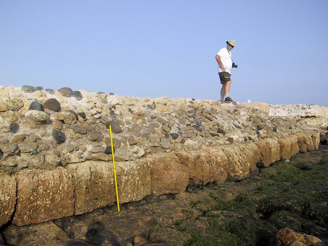
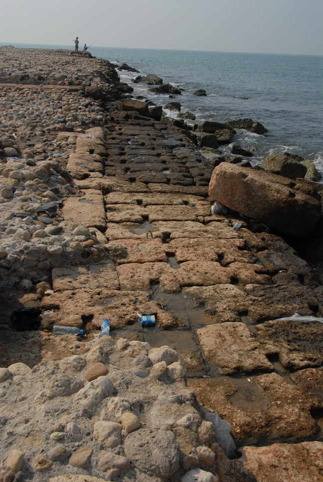
The design consists of two outer and inner stretcher blocks laid on
either side of five headers followed by a double row of headers. Each block was
secured to the adjacent blocks with enormous butterfly clamps set into the
upper surface of the stone (Figure 8). No clamps have survived, but deep
cuttings 35 cm long, 5 cm deep, and varying in width from 6 cm at the ends to 3
cm at their midpoints. There were up to 6 clamps per block. The size of the
clamp sockets suggests that they were originally wood rather than metal (Vann,
1995:533).
The upper
surface of the western mole is at 1.8 m above sea level, and where stretches of
the original paving stones remain, they are 1.3 m long and 0.63 m wide, laid
out in alternating rows of header and stretcher. Four cross walls are clearly
visible on the exposed surviving length of the western breakwater, are set at
34 m, 30 m, and 14 m apart to form the cells into which the concrete was
placed. Most of the cross-walls are 1.6 m thick, built with alternating courses
of headers and a line of double stretchers alternating with a header. One
cross-wall on the landward end is only 60 cm thick on the upper course,
consisting of a single line of stretchers, whilst it widens to a double row of
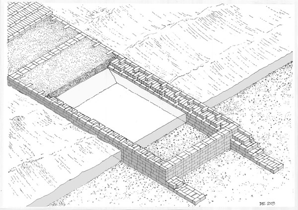
stretchers at a lower level. The cells were built out into the sea one by one,
and as each was completed it would have been in-filled with concrete (Figure 9).
This form of enclosure was not watertight and the compartments would have
flooded to sea level, requiring that the lowest stratum of the concrete be laid
underwater. The upper layer of the cells was then filled with a poorer quality
concrete, ultimately paved with stone slabs.
Beaufort’s
plan shows the colonnaded street, part of which is still visible today, running
inland from the harbour along the central axis of the basin. Aerial and land
surveys now show that the street was not on axis with the harbour, off centre
by some 20 m to the east. This was obviously a
deliberate design decision, but one that seems perverse when set in the context
of geometrically symmetry harbour basin. This deviation from symmetry would
make more sense if at some stage the Mezitli river or a canal leading from it
ran through the city and flowed into the harbour.
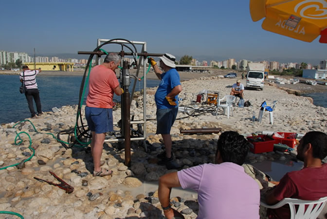
In
the short time available, the ROMACONS team took two cores on the west
breakwater, using our standard diamond core-drilling rig. We only worked above
water, since the top surface of the mole is currently 1.80 m above sea level.
The structure is so well preserved that we were able to drill down through the
complete height of the structure and well into the bedrock foundation (core
POM.2009.01). The coring was carried out over two days, on the 13th
and 14th August 2009. The first core, POM.2009.01, was drilled 5.7 m
in from the west face of the structure, 13.2 m from cross wall 01, and
approximately 5 m north of a point where bedrock protrudes through the
constructed part of the mole (Figure 10). The upper layers were very difficult
to drill through due to the friable nature of the binding mortar and the very
hard, large aggregate composed of closely packed, smooth riverbed cobbles and
pebbles, circa 15 to 20 cm in diameter.
The
mortar in the top 0.75 m is a poorly mixed, very pale brown material that is
fairly soft, containing much micro-aggregate and many pebbles circa 4-18 mm in
diameter. The micro-aggregate consists of rounded sea or river sand, including
many grains that are red, green, and blue. There are also many white nodules 4
– 8 mm in diameter that are either un-mixed lime or a product of the long
term reaction of the lime with the pozzolana, and also some small fibrous
nodules that could be pumice, brownish yellow in colour. There is a laminar
deposit across the core at a depth of 0.15 m below the top surface, either a product
of the evolution of the mortar, or laitance created during the pour.
From
-0.75-0.95 m the mortar was mostly ground away by the coring, although several
hard river stones remain, and some pumice lapilli, 20-30 mm in diameter.
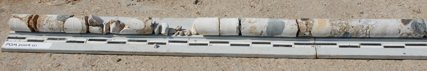
From
-0.95-1.40 m, the mortar is a very light grey to white, with limestone and
other smooth cobbles as aggregate. There are small fibrous pumice inclusions
and much rounded sand micro-aggregate, some brightly coloured as noted above.
(Figure 11)
At
a depth of -1.35 m there is a rounded lump of volcanic tuff, light greenish
brown in colour with yellow brown inclusions.
From-1.40-2.20
m, the mortar was the same type as above. Although poorly compacted, it
nevertheless is quite hard and varies in colour from white to light green. The
change in colour and composition may have to do with the proximity of the water
level. There are many voids in the material and many large white nodules, along
with lumps of fibrous pumice and particles of green sand, possibly olivine.
Below
-2.20 m the core consists of a yellowish red to pink limestone bedrock with a
layer of very fine mud just above it. It was impossible to determine precisely
where the mud came from, because it infiltrated the core hole each time the
tubes were removed to take out the cores. There are no apparent fissures in the
rock that could have contained the mud, so it probably had been deposited on
top of the bedrock by the river that flowed into the basin or harbour that
preceded the Roman mole.
The
core POM.2009.02 was taken on top of a flat concrete surface 0.49 m above sea
level, and inside the line of the blocks framing the upper part of the mole, 3
m from cross wall 02 and 3.1 m from the western marginal wall outer face
(Figure 12). The level surface seems to be the top surface of the lower level
of hydraulic concrete, exposed by erosion of the upper level of concrete after
the outside ashlar wall was breached at this point. The core hole depth was
0.90 m, although only 0.80 m of material was recovered. The mortar is clearly
pozzolanic in character, even containing some tuff aggregate. This same type of
tuff is seen in the Italian and Caesarea cores, and it probably arrived as an
accidental component of the pozzolana sand shipped from the Puteoli area. The
piece of limestone aggregate that forms the bottom of the core appears
weathered and does not show any traces of adhering mortar, so it probably
represents the bottom surface of this layer of concrete. The core tube went
approximately a metre beyond this point, seemingly going through layers of hard
and soft material, and jamming frequently. Nothing was recovered from this
layer, which may have consisted of a rubble footing.
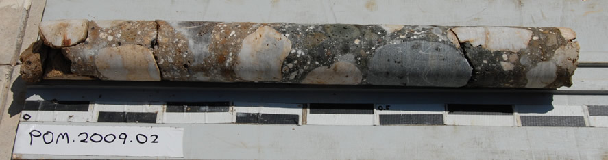
The mortar is
very homogeneous throughout the core: very hard, well mixed, and clearly
containing much pozzolanic material. The mortar of the upper portion is a
yellowish brown colour, drying to a very pale brown. The mortar contains many
nodules of pumice, 11-18 mm in diameter, and many angular fragments of a white
material, 2-10 mm across, that are either unburned limestone, un-mixed lime, or
a product of the pozzolana-lime reaction that has occurred over time. The
mortar is well compacted, but there are numerous very small spherical voids 1-3
mm across, perhaps resulting from some circumstance during placement, or from
the chemical evolution of the mortar. The aggregate is the same round river bed
limestone cobbles as noted in the first core, with occasional lumps of tuff
23-53 mm in diameter. The tuff also contains nodules of pumice. Wet, the tuff
is greenish blue in colour but dries to a light yellow brown. There is no sign
of the coloured sand particles seen in the upper portion of Core 01. (Figure
13)
From
-0.33 to -0.70 m there is a rapid change in colour of the mortar, to a bluish
green colour or possibly greenish grey, drying to a light greenish grey. At
-0.70 m the mortar returns to its brownish colour. In our other cores of
pozzolanic mortar, the bluish green colour is typical of mortar exposed to sea
water, or kept moist by sea water infiltrating the block.
At
-0.65 a small fragment of a fibrous material, possibly a reed or twig, D 6 mm,
was embedded in the mortar. At -0.75 m a small fragment of wood was embedded in
the surface of the core. Oxford University has carried out a C14 dating
analysis on the organic material recovered from the cores. Calibrated results
suggest that the concrete was placed around 147 AD ± 48.
After the
cores were extracted, the holes were filled with inert sand and sealed with a
weak hydraulic lime mortar and parts of the top section of the core and river
cobble aggregate, were reinserted as a cap to the filled core holes.
It is
apparent from the initial visual inspection that there are two distinctly
different concretes, the lower layers of a clearly hydraulic material and the
upper layers of a lime or weaker pozzolanic lime mortar. The chemical and thin
section analysis will confirm the specific make up of each. One very marked
difference between the Pompeiopolis concrete and that we have studied at other
sites is in the proportion of large aggregate to mortar. We have seen the
percentages range around 40% aggregate to 60% mortar in the concrete sampled at
sites along the Italian coast, Alexandria and Caesarea, whereas at Pompeiopolis
the percentage varies from 64 to 54% aggregate and 36 to 46% mortar. This ratio
is more akin to that found in Roman terrestrial structures (DeLaine, 1997:123).
In
line with the analysis and mechanical tests that have been carried out on
previous ROMACONS concrete samples; the cores have been taken to Italcementi’s
research laboratories in Bergamo, Italy. The C14 date corresponds well enough
with the date of the coin of Antoninus, suggesting that the coin commemorated a
recently completed project. All the data from the 2009 season will be added to
that collected from earlier work and will be published in a final report that
is currently being prepared.
Acknowledgements
We
wish to thank Dr Remzi Yağci of the Department of Archaeology, Dokuz Eylul
University in Izmir for his assistance and for generously agreeing to support
us with the permit request. This project would have been impossible without the
practical and scholarly assistance of Dr Nicholas Rauh, of Purdue University.
Thanks also go to Dr Enrico Borgarello, of Italcementi who has supported our
research and to his colleagues Mr Dario Belotti, Mrs Isabella Mazza, Dr E
Gotti, and Dr G Vola for their logistical and scientific input. We especially
thank Akin Kaymaz for his assistance in the field.
References
Beaufort,
F., 1817. Karamania, or a brief description of the South Coast of Asia-Minor
and of the Remains of Antiquity. London, esp. pp. 248-256.
Boyce, A.A. 1958. “The Harbour of Pompeiopolis. A Study in Roman
Imperial Ports and Dated Coins,” American Journal of Archaeology 62: 67-78.
DeLaine, J., 1997, The Baths of Caracalla, a study in the design,
construction, and economics of large-scale buildings in imperial Rome, Journal of Roman Archaeology Supplementary Series
Number 25. Portsmouth RI: JRA.
Oleson,
J. P., Brandon, C., Cramer, S. M., Cucitore, R., Gotti, E., and Hohlfelder, R.
L., 2004, “The ROMACONS Project: A Contribution to the Historical and
Engineering Analysis of the Hydraulic Concrete in Roman Maritime Structures,” International
Journal of Nautical Archaeology 33.2: 199-229.
Vann. R.L. 1995. “Survey of ancient Harbours in Turkey: the 1993 Season
at Pompeiopolis,” in XII Arastirma Sonuçlari Toplantisi, Ankara, pp. 529-534.
Figures
Figure 1 Location plan
(C. Brandon).
Figure 2 Sketch
impression of the 2nd Century AD harbour (C. Brandon).
Figure 3 Sir
Francis Beaufort’s plan (F. Beaufort 1817).
Figure 4 Antoninus
Coin, Obverse (American Numismatic Society).
Figure 5 Aerial
photograph (Prof. Remzi Yağci).
Figure 6 Plan
of harbour (C. Brandon, L. Vann).
Figure 7 Photograph
of ashlar marginal wall (C. Brandon).
Figure 8 Clamp
cuttings in blocks (J.P. Oleson)
Figure 9 Reconstruction
sketch of concrete laid in ashlar permanent formwork (C. Brandon).
Figure 10 Core
01 in progress (J.P. Oleson).
Figure 11 View
of core 01 (J.P. Oleson)/
Figure 12 Core
02 in progress (A. Kaymaz).
Figure 13 View
of Core 02 (J.P. Oleson).