Mooring Design
& Dynamics
A
Matlab® Package for Designing and Analyzing
Oceanographic Moorings and Towed Bodies
Reference: Marine Models Online, Vol(1), pp 103-157.
Richard K. Dewey
University of Victoria, BC, Canada
RDewey@UVic.CA
Users Guide
Latest Version 2.7 (November 2024)
 Mooring Design and Dynamics is a set of Matlab® routines (a toolbox) that
can be used to assist in the design and configuration of single point oceanographic moorings, the
evaluation of mooring tension and shape under the influence of wind and time varying baroclinic currents, and the
simulation of towed bodies. It was originally developed in 1998, and has had a few additions over the years.
It is not truly dynamic, in that at any one time the mooring is assumed to be in
a force balance (not moving), with no un-matched accelerations. The static model will
predict the tension and tilt at each mooring component, including the anchor, for which the safe mass
will be evaluated in terms of the vertical and horizontal tensions. Predictions can be saved to
facilitate mooring motion correction. Time dependent currents can be entered to predict the
dynamic response of the mooring.
Version 2.0 included the capability to predict the depth of towed bodies from
a moving ship with sheared currents, including the use of depressors and tow-floats. Version 2.3 (November 2016)
corrected the entire form and lift drag force formulation and it is strongly recommended that users upgrade to this version.
Version 2.4 (November 2021) needed to update the "plot mooring" routine, which stopped working with more recent versions of Matlab.
Version 2.6 (February 2024) is an essential fix (from v2.5) for surface moorings, and now has all surface floats partially submerged, at a minimum sufficient to provide the necessary buoyancy to keep the top buoy afloat. A new column in the "float" database was added and
is the weight of the float in air. The minimum percentage of float submerged is then the weight in air/buoyancy in water. Old mooring files will use a
nominal fraction of (weight/buoyancy) of 15% (0.15). Users can refine this by editing the database or deleting a float and re-entering with the weight is air.
Version 2.7 fixes a bug in how lift is applied to a tilted cylinder and all wire/rope elements in towed systems.
The package includes a preliminary database of standard
mooring components which can be selected from pull down menus. The database can be edited and
expanded (personalized) to include user specific components, frequently used fasteners/wires etc., or user-specific unique
oceanographic instruments. Once designed and tested, a draft of the mooring components can be plotted
and a list of components, including fasteners can be printed.
Mooring Design and Dynamics is a set of Matlab® routines (a toolbox) that
can be used to assist in the design and configuration of single point oceanographic moorings, the
evaluation of mooring tension and shape under the influence of wind and time varying baroclinic currents, and the
simulation of towed bodies. It was originally developed in 1998, and has had a few additions over the years.
It is not truly dynamic, in that at any one time the mooring is assumed to be in
a force balance (not moving), with no un-matched accelerations. The static model will
predict the tension and tilt at each mooring component, including the anchor, for which the safe mass
will be evaluated in terms of the vertical and horizontal tensions. Predictions can be saved to
facilitate mooring motion correction. Time dependent currents can be entered to predict the
dynamic response of the mooring.
Version 2.0 included the capability to predict the depth of towed bodies from
a moving ship with sheared currents, including the use of depressors and tow-floats. Version 2.3 (November 2016)
corrected the entire form and lift drag force formulation and it is strongly recommended that users upgrade to this version.
Version 2.4 (November 2021) needed to update the "plot mooring" routine, which stopped working with more recent versions of Matlab.
Version 2.6 (February 2024) is an essential fix (from v2.5) for surface moorings, and now has all surface floats partially submerged, at a minimum sufficient to provide the necessary buoyancy to keep the top buoy afloat. A new column in the "float" database was added and
is the weight of the float in air. The minimum percentage of float submerged is then the weight in air/buoyancy in water. Old mooring files will use a
nominal fraction of (weight/buoyancy) of 15% (0.15). Users can refine this by editing the database or deleting a float and re-entering with the weight is air.
Version 2.7 fixes a bug in how lift is applied to a tilted cylinder and all wire/rope elements in towed systems.
The package includes a preliminary database of standard
mooring components which can be selected from pull down menus. The database can be edited and
expanded (personalized) to include user specific components, frequently used fasteners/wires etc., or user-specific unique
oceanographic instruments. Once designed and tested, a draft of the mooring components can be plotted
and a list of components, including fasteners can be printed.
Download MD&D Files from Google Drive.
Installation
The latest version of the matlab toolbox
can be downloaded as a ZIP file, which inlcudes the subroutines, some example moorings files, and the
documentation from
mdd.zip, or visit the Mooring Design and Dynamics web page
for any recent updates and URLs to the
latest files.
The ZIP archives (ZIP and PC self-extracting .EXE) are approximately 2Mb in size.
Extract/copy the files into a local toolbox directory, possibly named
/matlab/toolbox/local/mdd (or what ever directory structure you may have for private toolboxes),
and add this directory to your
Matlab® path.
The programs are started and accessed entirely through a main GUI by
typing/starting »moordesign at the
Matlab® command prompt. To make this Users
Guide accessible from within
Matlab®, the contents of mdddoc.zip must be extracted
under the
Matlab® "help"
directory, in /matlab/help/toolbox/mdd. A Users Guide and model description can then be
accessed from within Matlab® by typing »mdd at the Matlab®
command prompt.
It is not necessary to install the Users Guide to use Mooring Design and Dynamics, but I strongly recommend reading the web version (most up-to-date0 version (here) as the code is old and quirky and most know issues are covered in the Users Guide.
If your
Matlab® path contains blanks, such as
"C:\Program Files\Matlab", then some of the load functions
will/may not work properly. This is because the load command can not have blanks in it. Unfortunately, the
easiest workaround is to install Matlab®
in a path without blanks (ugh!), i.e. "C:\Matlab". What ever...
Mooring Design and Dynamics is a toolbox for the
Matlab® application, and requires a
pre-installed version of Matlab®
to run (it is NOT a stand alone program). The first thing one needs to do, before
using MD&D to assist in the design and evaluation of an oceanographic
mooring, is get organized. One needs a clear definition of the mooring components, it's desired
dimensions, and the environment it will go into. It is suggested the user sketch out the mooring, make
a note of all the major components available, what height above the bottom they are to be deployed at,
what type of fasteners will be used, and what type/size of mooring wire will be used or is available.
All of this information is required before you can complete a mooring design and evaluate it. Then let
MD&D do the actual formal designing, evaluation, and plotting/listing
of the mooring. Alternately, to learn the basics and functionality of MD&D, one can start the program and get familiar with it's capabilities and
what features it has available from it's pull down menus using the example moorings and auxiliary files
provided with the program files. Also, despite the authors efforts, it is possible to enter data and
design moorings that are incompatible with the present code, and the program(s) and routines can be
made to "crash" if data is entered incorrectly. It is assumed the user will try to design meaningful
moorings and follow the suggestions provided here. And as with any development procedure, it is
suggested that you "save early, save often". If you encounter errors or program difficulties, please
"clear all" and reload the mooring. The GUI is "old", pull-down menus may not default to the display option (so always select),
and if there is an "Execute" button, this step (execute) is likely required to save the selections.
Do not assume the program is or the menus are robust to casual executions or error catching.
If problems persist, make sure you have the latest version.
The main menu (MD&D program) is started by typing
>>moordesign;
at the Matlab® command line prompt.
The Main Menu (showing all base options) with active links to each feature is shown
below.

The moorings that can be designed and tested using MD&D
are (at the moment) limited to single point (single anchor) configurations. It is assumed that the user has thought
about the type of mooring, the hardware available to build it, and the environment the mooring will be deployed in.
A rough sketch and/or list of the components and
their anticipated positions along the mooring should be drafted before you begin with
MD&D
. The list of components used by MD&D is intentionally exact (i.e. each
shackle MUST be included). The most common problem I get asked to solve when using MD&D
is that user did not put "connectors" in between mooring elements.
The code needs to know where one element/component ends and the next distinct component begins,
and so just like in a real mooring I insist that the design have connectors (i.e. at least a shackle) between
mooring components. A typical mooring that won't work is: a float, some rope/wire, an instrument, some more rope/wire and an anchor.
The working version of this mooring is: a flaot, a shackle, some rope/wire, a shackle, an instrument, a shackle, more rope/wire,
a shackle, an anchor. This will work. Once designed and tested, the actual list of mooring components (including shackles),
broken down by each different type can be printed, and can actually used as a shopping/packing list.
Moorings are designed from the top down, starting with a float (positive buoyancy
device) and ending with an anchor (negative buoyancy device). Non-sense moorings can be designed, but will have
meaningless solutions or may cause MD&D to crash. It may be necessary to save a
mooring/towed body configuration early, and after a "crash", execute the "Clear All" option from the main menu to clear
memory. Then re-load the file in order to continue. Finally, before deploying a mooring, please read the Disclaimer.
I have added the capability of estimating the tension and fall speed during a free fall
descent (anchor first or last deployments).
This is accomplished by adjusting the uniform (at all depths) vertical velocity (relative to the mooring), until
the weight under he anchor (displayed when a solution is found) is zero (=0). The W associated with this state will be the approximate fall
speed for a free-fall vertically aligned mooring. The tensions in the
wire (which may be large) during a free-fall descent will then be displayed/available.
Warning: This "work-around" does not include any prediction skill while the mooring is adjusting (aligning) to a vertial hang position.
The top (float) of anchor-last free-fall moorings can penetrate to depths
deeper than the static depth, due to inertia and wire angles during release (swinging).
Also, for an anchor-last deployment, the
mooring will not be vertical for the first part of the descent (while the anchor falls/swings below the floats),
and the fall speed solution will not represent this period.
I have heard of the top components of "anchor last" moorings reaching depths deeper than the final vertical alignment/position
of the mooring, so I caution about pushing the pressure ratings of devices too tightly.

The towed bodies that can be designed and tested with MD&D
are of three basic configurations. First is a simple heavy object (net negative buoyancy) and a segment of wire.
However, to facilitate the solution, a virtual "top-of-tow-rope" (floatation) device MUST be placed at the top of the
towed body configuration (see the example in tow001.mat). This is used by the program to "identify" the water surface.
This device has no mass or size, and does not affect the solution, it only assists the program in determining where the
in-water wire and out-of-water wire point is located.
The second type of towed body configuration allowed by MD&D would include a heavy (negative
buoyancy) device(s) (depressor) some where along the tow wire. This is often used to force the towed body to greater depths. The third
configuration has a single floatation (positive buoyancy) device (riser) along the tow
wire, which may or may not break the surface. This is often used to "de-couple" the ship motion from the towed body. In
addition to setting the ship velocity (U=east and V=north), the user
can set the water column velocity profiles [U(z), V(z), W(z)], as might be recorded by an on-board ADCP. Both of these
velocities should be in absolute Earth coordinates (relative to the Earth). Highly
sheared flows will cause the towed body to get pulled far to the side, or even ahead of a slowing moving tow ship.
The user should specify the approximate height (i.e. 5 m) of the towing block (or A-frame) above the water.
This will allow MD&D to estimate the amount of wire out of
the water (from the water surface to the A-frame), which for light towed bodies or high speed tows,
can be significant. The total wire length (from tow body to A-frame) will then be displayed. The size of the towing ship
plotted by MD&D is proportional to the height of the A-frame.
I do not officially provide help. But...
I do want this program to work for you. I have been told the program is "quirky" and takes some getting used to. Do not assume it works
by clicking any oder of buttons and features, as I have not made the code idiot proof.
Follow each menu and sequence methodically, and most information is only "captured" when the "execute" button is
clicked.
It was written when Matlab first released a GUI interface feature (1997), so this represents both Mathworks and my first attempt at a GUI program.
Most of the time I get people contacting me with errors and moorings that don't work, there is a simple explanation.
MD&D assumes the mooring you have "built" through the menu interface is EXACTLY like the real mooring as it will be in the water.
In particular, it MUST have connectors joining the different mooring components.
Therefore both your real-world mooring and the MD&D mooring MUST have (at a minimum) shackles to connect the mooring elements.
MD&D (the code) uses these shackles to know where to break the mathematical solution into segments. Shackles are wonderful things
and it is difficult to use too many. Or at least it is in my code. So, please, make sure you insert a shackle in between every
different mooring component. Then see if you still get errors.
If you do, save the mooring to a MAT file and send it to me.
If I have time, I will try to reproduce the error and see if I can help you fix the problem. If I cannot, oh well, at least you didn't
have to buy MD&D. :)
- Getting Started
- A Word About Moorings
- A Word About Towed Bodies
MD&D
- The Main Menu
- Design New Mooring Initialize a mooring design and all variables.
- Design New Towed Body Initialize a towed body design and all variables.
- Load Existing Mooring/Towed Body Load a previously designed and saved mooring/towed
body.
- Save a Mooring/Towed Body Save the present mooring/towed body.
- Add/Modify In-Line Mooring Elements Add/Edit the present mooring configuration.
- Add/Modify Clamp-on Devices Add/Edit the present mooring/towed body clamp-on devices.
- Add/Modify A Towed Body Add/Edit the present towed body configuration.
- Set/Load Environmental Conditions Set Currents, Wind, Ship velocity.
- Display Currents Display the velocity and density values.
- Evaluate and Plot 3-D Mooring/Towed Body Once designed, evaluated
the mooring under the specified environmental conditions.
- Display Mooring/Towed Body Elements|Print Display (or prints) positions
(and, if evaluated, tensions) of each mooring component and a component summary.
- Plot Mooring|Print Plots (or prints) mooring components.
- Set Desired Depth [m] Enter the desired depth for a towed body, predict the wire
length.
- Add/Examine Elements in Database Edit the mooring component database.
- Make/Load/Show a Movie Make a
Matlab® movie of the mooring forced by time varying currents.
- Clear All Clears all MD&D
variables and figures (state wide re-initialize).
- Whos Displays list of variables, including global matrices.
- Close Close all figures and exit MD&D.
- The Mathematical Solution
- Examples
- Disclaimer
- References

The Main Menu provides access to all the major functions available in MD&D for both moorings (top panel) and towed bodies (low panel).
Initially, however, when no mooring or the necessary environmental
conditions are loaded into memory, only a sub-set of options will be displayed by the Main Menu. These include
the
ability to design a new mooring/towed body, load a mooring/towed body file, and edit/examine the database. As
a mooring or towed body is designed and analyzed, the number of displayed options in the Main Menu increases.
Shown in the top Main Menu figure is a relatively complete Main Menu, showing most functions, after a mooring
has
been loaded. The lower Main Menu figure shows the Main Menu after a Towed Body configuration has been
loaded/designed. These menus are nearly identical, except for the options of plotting the mooring
and making a times series of mooring solutions or movie (available only for moorings),
and the option for specifying the desired depth of the towed body (available on only for towed body
configurations). The size of the Main Menu on your computer screen can be re-sized by dragging one of the corners.
MD&D will then remember this new size the next time it is started.
Design New Mooring Initialize mooring design.
Design New Towed Body Initialize towed body design.
Load Existing Mooring/Towed Body Load a previously designed and saved mooring/towed
body.
Save a Mooring/Towed Body Save the present configuration into a mat file.
Add/Modify In-line Elements Add/Edit the in-line mooring/towed body components.
Add/Modify Clamp-on Devices Add/Edit any clamp-on mooring/towed body components.
Add/Modify A Towed Body Add/Edit the present towed body configuration.
Set/Load Environmental Conditions Set Currents.
Display Currents/Ship Speed Display velocity and density values for moorings,
and in addition for towed bodies, display the ship velocity components (East/North).
for towed bodies.
Evaluate and Plot 3-D Mooring/Towed Body Once designed, a mooring/towed body
can be evaluated under varying environmental conditions.
Display Mooring Elements|Print Display positions (and tensions) of each
mooring component and a component summary.
Add/Examine Elements in Database Edit the mooring component database.
Make/Load/Show a Movie For time varying currents.
Clear All Clears all MD&D variables/figures.
Whos Displays list of all variables (including global).
Close Exit from MD&D and return to MATLAB
command window.
If any of the menu text strings do not fit the menu buttons, or are not legible, then one
can
change the size of the Menu fonts used by MD&D by editing the first
executable line of moordesign.m, fs=12; immediately following the global declarations. An attempt to auto-scale
the
menu font size based on screen resolution is made.
Return to TOC of Users Guide
This function clears
the component list, and presents the user with the "Modify Mooring Design" window. This is the
primary menu/function from which mooring elements can be added (from the database) or deleted to/from
a mooring. By default, mooring elements (components) are added from the top (element one) to the
bottom of the mooring. The top element is usually a floatation device, the bottom element usually an
anchor. All moorings need to have at least some positive buoyancy elements (floatation) and negative
buoyancy elements. Non-sense moorings will likely cause the program to crash. Just as in a real
mooring, components MUST be separated by appropriate fasteners (e.g. shackles), even if the
adjacent mooring components are both wire or rope elements. The intent is to have the solution and list of
mooring components be as complete and accurate as possible, leaving nothing out which is required for
actually building the mooring. Other mooring programs allow you to not specify an anchor, or have
adjacent components without fasteners. MD&D requires you to be
accurate and complete. This forces one to think about the safe operating loads on each component, as
a mooring is only as strong as it's weakest link. A good mooring should have consistent components
(i.e. fasteners) which reflect the anticipated loads and tensions, without wasting over-size
components. Sometimes, due to the dimensions of certain devices, shackles of specific size are
necessary (i.e. the drop shackle for an Interocean Acoustic Release is a 1 inch anchor shackle).
Fitting these specific components with the rest of the mooring may require a series of shackles, and
it is recommended that all of these components be included in the mooring design and analysis. MD&D was designed to do exactly this, producing the most accurate analysis
and complete list of components.

Element to Add/Insert This numeric string is editable
(click on the number with the mouse), and must either be the next "free" element (number of present
elements plus 1, default) to add, or an existing element number to insert a new element and bump the
remaining elements below this.
Delete Element Editable string, where
an existing mooring element number is entered in order to delete this element. You should "click"
Display Elements both before and after deleting an element to confirm the
updated list of mooring elements and their element number.
Component Type: Floatation
(and other mooring component types) This is a pull down menu. Click on the  button to reveal the available list of database component types. They include: Floatation, Wire, Chain and Shackles, Current Meter, Acoustic Release, Anchor, and Component: Misc Instrument. Select a component type by clicking on the name of the type.
Fasteners (shackles and rings) are listed under Chain and Shackles.
61in ORE (and other available mooring components) A pull-down menu to select the
desired mooring component from a list of the available database components for this mooring component
type. Click on the button to reveal the available list of components, then
click on the desired component. The mooring element list will automatically be updated and displayed
in the Matlab®
Command Window.
Display Elements This button will
re-generate an updated list of the present mooring elements and their respective number in the main
Matlab®
Command Window.
Close Closes this menu, keeping the present
mooring components in memory, and returning to the Main Menu. It would be advisable
to save a complicated mooring after each major modification.
button to reveal the available list of database component types. They include: Floatation, Wire, Chain and Shackles, Current Meter, Acoustic Release, Anchor, and Component: Misc Instrument. Select a component type by clicking on the name of the type.
Fasteners (shackles and rings) are listed under Chain and Shackles.
61in ORE (and other available mooring components) A pull-down menu to select the
desired mooring component from a list of the available database components for this mooring component
type. Click on the button to reveal the available list of components, then
click on the desired component. The mooring element list will automatically be updated and displayed
in the Matlab®
Command Window.
Display Elements This button will
re-generate an updated list of the present mooring elements and their respective number in the main
Matlab®
Command Window.
Close Closes this menu, keeping the present
mooring components in memory, and returning to the Main Menu. It would be advisable
to save a complicated mooring after each major modification.
Return to The Main Menu
Return to Users Guide TOC

This function clears
the component list (all memory), and presents the user with the "Modify Towed Body Configuration" window.
This is the primary menu/function from which towed body elements can be added (from the database) or deleted
to/from a configuration. By default, towed body elements (components) are added from the bottom (element one)
to
the top of the tow rope. The top element must be the "top-of-tow rope" floatation device, the bottom element
the towed body. All towed bodies need to have at least some negative buoyancy elements and may contain a single
floatation device. Non-sense tow body configurations will likely cause the program to crash. Just as in a real
towed body, components MUST be separated by appropriate fasteners (e.g. shackles), even if the
adjacent components are both wire or rope elements. The intent is to have the solution and list of
components be as complete and accurate as possible, leaving nothing out which is required for
actually building/simulating the towed body.


Three different towed body configurations can be evaluated with MD&D.
These include a simple heavy towed body suspended by a single wire element (see figure above). The
configuration
may be sufficient for most towed body evaluations. An example is stored in the file TOW001.MAT included with
MD&D. The second type of towed body will include a depressor or weight
(negative buoyancy device) at some location along the tow wire
(or more correctly between wire segments). Such a configuration is
shown here on the right and on the
Marlin page at OSU.
The third configuration includes a floatation device at some distance along the tow
wire. Depending on the weight of the tow body, it's drag, the currents and ship speed, the float may or may not
break the surface. Such a spacer is often used to buffer the towed body from ship motion. Once a towed body has been
designed, the following menu is identical to the Modify Towed Body menu.

Element to Add/Insert Bottom-to-Top This numeric string is editable
(click on the number with the mouse), and must either be the next "free" element (number of present
elements plus 1, [default]) to add, or an existing element number to insert a new element and bump the
remaining elements below this. The action is not taken until the "Execute" button is pressed.
Delete Element Editable string, where
an existing towed body element number is entered in order to delete this element. You should "click"
Display Elements both before and after deleting an element to confirm the
updated list of mooring elements and their element number. The delete action is not taken until the "Execute" button is
pressed.
Component Type: Misc Instrument
(and other towed body component types) This is a pull down menu. Click on the
button to reveal the available list of database component types.
Select a component type by clicking on the name of the type.
Fasteners (shackles and rings) are listed under Chain and Shackles.
Component: Heavy Sphere (and other available components) A pull-down menu to select the
desired towed body component from a list of the available database components for this component
type. Click on the button to reveal the available list of components, then
click on the desired component. The list of component will not be updated until the "Execute" button is pressed. The "Heavy
Sphere" in the default database, represents a test device for towed bodies. It is a sphere with net negative buoyancy
(sinks), and can be used as a template for other simple towed bodies.
Enter Ship Velocity [U V] (m/s) This is where the user specifies and changes the ship velocity
for the towed body. The ship velocity is assumed to be in Earth coordinates, with U = East velocity and V = North velocity,
both given in metres per second (m/s). Note that 1 knot is 0.514 m/s. Use MATLAB (or other calculator) to convert a speed
and compass direction to components using "speed*exp(i*(90-heading)*pi/180)", where heading is clockwise from true north and
U is the real part and V is the imaginary part of the answer. NOTE: If the water column velocity profile is given in
absolute velocities relative to the Earth (i.e. navigated ADCP data), then the ship velocity is the velocity OVER LAND (i.e. as reported by a GPS navigation system. If the water column velocity is not know, or set to zero (default), then the
important ship velocity is that relative to the surface water. If both are absolute (i.e. relative to land), then they will
give the same result. For example, a ship moving in the X (East) direction at one knot, is equivalent to a stationary ship
in a U=-0.514 m/s current.
Height of A-Frame Block Above Water (m) This number sets the scale of the ship, and also
determines the length of wire out of the water, from the surface to the A-frame block. For light tow bodies, or fast towing,
there can be a significant amount of wire out of the water, be tween the surface and the block.
MD&D will estimate this length of wire, so that the reported wire length is from the block to the towed body. No
wind drag is calculated in the "out-of-water" wire, so a hanging catenary shape is assumed. As with the
real world, the angle of the towed body from the ship pivots at the block. If the height of the A-
frame is set to zero, no ship is plotted (ship size scales with A-frame height).
Execute Add-Insert-Delete Operation Once the component has been selected for addition, insertion,
or deleting, this button executes the procedure.
Display Elements This button will
generate a list of the present towed body elements and their respective number in the
Matlab® Command Window.
Close Closes this menu, keeping the present towed body
components in memory, and returning control to the Main Menu. It would be advisable to save a complicated towed body after each major modification.
Return to The Main Menu
Return to Users Guide TOC
 Opens an operating system window, similar to the one shown here, from which
the user can select a disk, directory, and MAT file containing a previously saved
mooring or data. This same window is used to load a previously saved movie of a
time dependent mooring simulation or environmental data. Some default and test
moorings and movies are included with this package (including least the list shown here), with some
time dependent current profiles moorings (*ts.mat). Click on (highlight) the desired file and then
click
Opens an operating system window, similar to the one shown here, from which
the user can select a disk, directory, and MAT file containing a previously saved
mooring or data. This same window is used to load a previously saved movie of a
time dependent mooring simulation or environmental data. Some default and test
moorings and movies are included with this package (including least the list shown here), with some
time dependent current profiles moorings (*ts.mat). Click on (highlight) the desired file and then
click  , or double click on the filename (depending on the operating system).
Return to The Main Menu
Return to Users Guide TOC
 Opens an operating
system window, similar to the one shown here, from which the user can select a disk, directory, and
MAT filename into which all necessary mooring information or environmental data
is saved. This mat file can then be loaded later to further evaluate, view,
modify, or analyze the mooring. Click on an existing filename to overwrite, or enter the filename.
This list shows some of my mooring designs from a project in Juan de Fuca in 1997, including three
thermistor chain and two ADCP moorings. Time series of current profiles recorded by the ADCPs where
then used to "simulate" mooring motion. The thermistor depths where then corrected. These "weakly"
taut moorings had 15 m excursions during peak (1.2 m/s) currents, which where simulated to within 1%
of the recorded top and bottom pressure records.
Opens an operating
system window, similar to the one shown here, from which the user can select a disk, directory, and
MAT filename into which all necessary mooring information or environmental data
is saved. This mat file can then be loaded later to further evaluate, view,
modify, or analyze the mooring. Click on an existing filename to overwrite, or enter the filename.
This list shows some of my mooring designs from a project in Juan de Fuca in 1997, including three
thermistor chain and two ADCP moorings. Time series of current profiles recorded by the ADCPs where
then used to "simulate" mooring motion. The thermistor depths where then corrected. These "weakly"
taut moorings had 15 m excursions during peak (1.2 m/s) currents, which where simulated to within 1%
of the recorded top and bottom pressure records.
Return to The Main Menu
Return to Users Guide TOC
As with Designing a New Mooring, this is the primary working menu used to modify (add and
delete) in-line mooring elements from a mooring. More mooring components will be "in-line". These components
are
distinguished from "clamp-on" devices, which would commonly be attached to a wire/rope segment.

Element to Add/Insert. This numeric string is editable
(click on the number with the mouse), and must either be the next "free" element (number of present
elements plus 1, default) to add, or an existing element number to insert a new element and bump the
remaining elements below this.
Delete Element Editable string, where
an existing mooring element number is entered in order to delete this element. You should "click"
Display Elements both before and after deleting an element to confirm the new
list of mooring elements and their element number.
Load Different Database This option allows a user to maintain a variety of
databases,
and
load a new or user specific database of mooring components as necessary. When loaded, the component type and
components displayed in the following menu items may change.
Current Meter (and
other mooring component types) This is a pull down menu. Click on the button
to reveal the available list of database component types. They include: Floatation,
Wire, Chain and Shackles, Current Meter, Acoustic Release, Anchor, and Misc
Instrument. Select a component type by clicking on the name of the type. Fasteners
(i.e. shackles, rings, swivels, etc.) are listed under Chain and Shackles.
Aanderaa RCM-7 (and
other mooring components) A pull-down menu to select the desired mooring component from a list of the
available database components for this mooring component type. Click on the
button to reveal the available list of components, then click on the component. The mooring element
list will automatically be updated once this component has been selected.
Execute Update Push this button to execute the desired update to the in-line mooring
components once the index, type and device have been selected. This was added as a confirmation and a safe guard
to
minimize errors in changing moorings.
Display Elements This button will
generate a list of the present mooring elements and their respective number in the main Matlab®
Command Window.
Global Replace This option allows a user to globally replace/substitute one type
of mooring component with another from the database. Selecting this option brings up the
Global Replace menu. Both in-line and clamp-on devices can be universally replaced.
Close Closes this menu, keeping the present mooring
components in memory, and returning control to the Main Menu. It would be advisable to save a complicated mooring after each major modification.
Return to The Main Menu
Return to Users Guide TOC
As with In-Line Elements, this menu is used to add/modify any clamp-on mooring components. Such
components
would most naturally (in the real world) be attached to a wire or rope segment. However, This program allows
the
user
to specify the height of the desired component above the bottom, and the program will determine which in-line
mooring
component the clamp-on device is attached.

Clamp-on Device to Add/Insert. A separate list of clamp-on devices is stored, and
this
index is a non-sequential pointer to the clamp-on devices. When the mooring components are
displayed, a separate list is displayed if there are any clamp-on devices. Each clamp-on
device is
listed with it's index, and this displayed index should be used with adding/deleting clamp-on devices.
Usually,
this
index is incremented, but the device heights may not be sequential.
Delete Clamp-on Element Editable string, where
an existing clamp-on device number (index) is entered in order to delete this device. The deletion is not
executed until the "Execute Update" button is pushed. You should "click"
Display Elements both before and after deleting an element to confirm the new
list of mooring elements/clamp-on devices and their associated element number/index.
Load Different Database This option allows a user to maintain a variety of
databases,
and
load a new or user specific database of mooring components as necessary. When loaded, the component type and
components displayed in the following menu items may change.
Misc Instrument (and
other mooring component types) This is a pull down menu. Click on the button
to reveal the available list of database component types.
Branker TR1000 (and
other mooring components/devices) A pull-down menu to select the desired mooring component from a list of the
available database components for this mooring component type. Click on the
button to reveal the available list of components, then click on the component. The mooring component
lists will be updated only after the "Execute Update" button is pushed.
Display Elements This button will
generate a list of the present mooring elements and their respective number in the main Matlab®
Command Window.
Execute Update Once selected, this button incorporates the changes
(additions/deletions)
into the mooring array.
Close Closes this menu, keeping the present mooring
components in memory, and returning control to the Main Menu. It would be advisable to save a complicated mooring after each major modification.
Return to The Main Menu
Return to Users Guide TOC

As with In-Line Elements,
this menu is used to add/modify in-line components associated with a towed body. Such components
would most naturally (in the real world) include the towed body, fasteners, wire/rope, and the mandatory
"top-of-tow-rope" device. Three towed body configurations are possible in MD&D.
First is a simple towed body, with a body, wire, and "top-of-tow-rope" device (The "top-of-tow-rope" device is necessary as,
the wire actually continues out of the water to the block at the A-frame, but MD&D needs to
know where the surface is. The second available configuration would include a "heavy" (sinking) weight at some distance
along the tow wire. This configuration is sometimes used to force a towed device to depths deeper than would be
accomplished without the weight. The third configuration involves placing a "float" along the tow wire, effectively de-
coupling the towed body from any pitching and heaving of the ship. MD&D allows for a single
in-line float. Multiple floats will confuse the program, as it needs to split the mathematical solution into two parts
(ahead-of and behind the float).
Element to Add/Insert. This editable number specifies the next towed body element to add or
modify in the configuration. For towed bodies, the program works from the bottom (towed body) to the top (top-of-tow-rope).
Usually, the index is incremented to be one larger than the number of elements presently in the tow line. The addition is
not preformed until the "Execute" button is pressed.
Delete Element Editable string, where
an existing towed body component number (index) is entered in order to delete this device. The deletion is not
executed until the "Execute Update" button is pushed. You should "click"
Display Elements both before and after deleting an element to confirm the new
list of mooring elements/clamp-on devices and their associated element number/index.
Load Different Database This option allows a user to maintain a variety of
databases, and load a new or user specific database of mooring/towed body components as necessary. It might be desireable to
maintain separate databases for towed bodies and moorings, especially if the database(s) becomes large.
When loaded, the component type and components displayed in the following menu items will change.
Component Type: Floatation (and
other towed body component types) This is a pull down menu. Click on the button
to reveal the available list of database component types.
Component: Top of Tow Rope (and
other towed body components/devices) A pull-down menu to select the desired component from a list of the
available database components for this component type. Click on the
button to reveal the available list of components, then click on the component. The working mooring component
lists will be updated only after the "Execute" button is pressed.
Change Length of Wire Element # For a towed body, the most common change will simply be a
lengthening or shortening of the tow rope. To facilitate this change, rather than deleting and adding a new wire/rope
element each time, the user can select the wire/rope element to change (the element number is listed in the Command Window
when the Display Elements button is pressed), and then puss this button to change the wire/rope
length. A new window will open from which the user can edit the wire length.
Enter Ship Velocity [U V] (m/s) This is where the user specifies and changes the ship velocity
for the towed body. The ship velocity is assumed to be in Earth coordinates, with U = East velocity and V = North velocity,
both given in metres per second (m/s). Note that 1 knot is 0.514 m/s. Use MATLAB (or other calculator) to convert a speed
and compass direction to components using "speed*exp(i*(90-heading)*pi/180)", where heading is clockwise from true north and
U is the real part and V is the imaginary part of the answer. NOTE: If the water column velocity profile is given in
absolute velocities relative to the Earth (i.e. navigated ADCP data), then the ship velocity is the velocity OVER LAND (i.e. as reported by a GPS navigation system. If the water column velocity is not know, or set to zero (default), then the
important ship velocity is that relative to the surface water. If both are absolute (i.e. relative to land), then they will
give the same result. For example, a ship moving in the X (East) direction at one knot, is equivalent to a stationary ship
in a U=-0.514 m/s current.
Height of A-Frame Block Above Water (m) This number sets the scale of the ship, and also
determines the length of wire out of the water, from the surface to the A-frame block. For light tow bodies, or fast towing,
there can be a significant amount of wire out of the water, be tween the surface and the block.
MD&D will estimate this length of wire, so that the reported wire length is from the block to the towed body. No
wind drag is calculated in the "out-of-water" wire, so a hanging catenary shape is assumed. As with the
real world, the angle of the towed body from the ship pivots at the block. If the height of the A-
frame is set to zero, no ship is plotted (ship size scales with A-frame height).
Execute Add-Insert-Delete Operation Once the component has been selected for addition, insertion,
or deleting, this button executes the procedure.
Display Elements This button will
generate a list of the present towed body elements and their respective number in the
Matlab® Command Window.
Close Closes this menu, keeping the present towed body
components in memory, and returning control to the Main Menu. It would be advisable to save a complicated towed body after each major modification.
Return to The Main Menu
Return to Users Guide TOC
 This menu allows a user to make global or wholesale changes to the mooring components of an existing mooring.
Display Elements button lists in the main Matlab command window all mooring
components and a summary or tally of how
many of each different type of mooring component is included. For wire and rope components, the total length
of material is displayed, even if this is divided into multiple segments in the mooring.
Change All. The mooring summary list is accessible from the Change All pull down
menu, from which the user can select a mooring component that has multiple occurrences, and then select an
alternate component to replace these.
Use the Type and Component menus to select the new
component (e.g. globally replace 1/2'' shackles with 5/8" shackles) .
The change does not occur until the Change button is pressed. Be careful, it is
possible to remove major
components, (e.g. floats) and globally replace them with inappropriate device types (e.g.
anchors). The available mooring components displayed are from the default database file (mdcodes.mat).
The Close button closes this global change window and sends control back to the
Modify Elements window.
Return to Modify Mooring
Return to The Main Menu
Return to Users Guide TOC
") Enter/Edit Velocities Manually to enter the velocities [U(z), V(z), W(z) and z]
using the keyboard.
Load / Save Velocity File If velocity profile data has
already been entered and/or saved, it can/should be reloaded or saved at this time.
Enter / Edit Densities Manually Enter or Load a density [kg/m3] profile.
The mooring solution depends very weakly on density, but if it is important, one can modify it.
Load / Save Density File If density profile data has
already been entered and/or saved, it can/should be reloaded or saved at this time.
Enter Winds Allows the user to specify a surface wind, which will apply an extra
velocity kick (2% of wind speed) to the upper ocean current speeds.
Help brings up a simple text window with a brief description of the types of
environmental data which can
be entered.
Enter/Edit Velocities Manually to enter the velocities [U(z), V(z), W(z) and z]
using the keyboard.
Load / Save Velocity File If velocity profile data has
already been entered and/or saved, it can/should be reloaded or saved at this time.
Enter / Edit Densities Manually Enter or Load a density [kg/m3] profile.
The mooring solution depends very weakly on density, but if it is important, one can modify it.
Load / Save Density File If density profile data has
already been entered and/or saved, it can/should be reloaded or saved at this time.
Enter Winds Allows the user to specify a surface wind, which will apply an extra
velocity kick (2% of wind speed) to the upper ocean current speeds.
Help brings up a simple text window with a brief description of the types of
environmental data which can
be entered.
Return to The Main Menu
Return to Users Guide TOC
 The Enter
buttons bring up (yet) another menu
which allows the user the type in a string of delineated (spaces, commas) values for each of the
desired profiles [e.g. U(z) and z], each with the exact same number of values, starting from the top
(surface) value to the bottom value, which is ALWAYS associated with z(n)=0 meters, where n is the
total number of values making up the velocity profile(s). By default the V(z) and W(z) profiles are
set to zeros. The height of the velocity and density profiles determines the water depth which the
mooring is in.
Save Velocities Opens a system window (section 1.3) to save the
velocity (environmental) data into a standard
Matlab® mat file. This same environmental
data can be re-loaded using the Load Environmental Conditions option (section 1.5).
Help opens a simple text window with simple instructions as to how to enter meaningful velocity
profile data as a text string (i.e. current values in m/s from top to bottom, where a bottom must
be entered at z=0).
The Enter
buttons bring up (yet) another menu
which allows the user the type in a string of delineated (spaces, commas) values for each of the
desired profiles [e.g. U(z) and z], each with the exact same number of values, starting from the top
(surface) value to the bottom value, which is ALWAYS associated with z(n)=0 meters, where n is the
total number of values making up the velocity profile(s). By default the V(z) and W(z) profiles are
set to zeros. The height of the velocity and density profiles determines the water depth which the
mooring is in.
Save Velocities Opens a system window (section 1.3) to save the
velocity (environmental) data into a standard
Matlab® mat file. This same environmental
data can be re-loaded using the Load Environmental Conditions option (section 1.5).
Help opens a simple text window with simple instructions as to how to enter meaningful velocity
profile data as a text string (i.e. current values in m/s from top to bottom, where a bottom must
be entered at z=0).
Back to Load Environmental Conditions
Return to The Main Menu
Return to Users Guide TOC

Enter the velocity values
in m/s separated by either spaces or commas, as a text string starting with the top (highest) value and
ending with the velocity value at the bottom (z=0), which in most cases should be 0 m/s. There is no
limit to the number of velocity values in a profile. Alternately, view the contents of the provided velocity
mat files included with the package to see the data format, and make/load you own velocity data from
the keyboard, a model, or measured currents and save these into a mat file. The displayed values make
up the default velocity profile with speeds of 1.0, 0.6 and 0 m/s, respectively.
OK will accept
these values and potentially bring up the Enter Heights menu.
Help
displays a simple text window of help for entering the velocity profile data.
Back to Load Environmental Conditions
Return to The Main Menu
Return to Users Guide TOC

Enter the height values in m for the associated velocity data,
separated by either spaces or commas, as a text string starting with the top (highest) value and ending at
the bottom (z=0). The number of Z values must be the same as the number of velocity values already
entered. Alternately, view the variables in the provided velocity mat file (vel001.mat) included with the
package to see the
data vector format, and make/load you own velocity and density profile data from the keyboard, a
model, or measured values and save these into an appropriately named mat file. The displayed values
are the default heights: 120, 10 and 0 meters.
OK will accept these values.
Help displays
a simple text window of help for entering the velocity profile data.
Back to Load Environmental Conditions
Return to The Main
Menu
Return to Users Guide TOC

Enter either the density values or the height values for the density profile.
The solution needs a local density value, so you can enter a specific density structure, or default
to a simple stratified ocean [1024 kg/m3 at surface 1026 kg/m3 at bottom].
Save Density Profile brings up the save
Matlab® file menu for saving the density
profile data for future retrieval.
Help brings up a simple text window describing the minimum
data entry procedures for entering density profile data as a space or comma delineated text string.
Back to Load Environmental Conditions
Return to The Main Menu
Return to Users Guide TOC

Enter either the density values or the height values for the density profile as
text strings procedures by either spaces or commas. The solution needs a local density values (stored
in vector/variable "rho"), so you can enter a specific density structure, or default to a simple linearly
stratified ocean [1024 kg/m3 at surface, 1026 kg/m3 at bottom].
OK brings
up a similar window to enter or edit the heights for the density values.
Help brings up a
simple text window describing the minimum data entry procedures for entering density profile data as
a space or comma procedures text string.
Back to Load Environmental Conditions
Return to The Main Menu
Return to Users Guide TOC

Enter the wind speed [m/s] and direction [degrees from North in
meteorological convention, i.e. the direction from which the wind is blowing]. The 2% velocity "kick"
penetrates to depths below the surface at approximately 1 m for every m/s of wind speed (regardless
of the density profile), so a 10 m/s wind penetrates an additional linearly decreasing velocity
profile down about 10 m in the direction of the wind (no Ekman spiral). The maximum wind penetration
is 80% of the water column, assuming that a bottom boundary layer will exist within which wind
forcing is negligible/dampened.
OK returns and stores the surface wind vectors (in East and
North components).
Help brings up a simple text window describing the minimum data entry
procedures for entering environmental data.
Back to Load Environmental Conditions
Return to The Main Menu
Return to Users Guide TOC
Pressing this button will display the current velocity and density profile values
in the main Matlab®
Command Window. To plot these profiles, one can simply enter regular
Matlab®
plotting commands at the command prompt. I have not included a profile plotting set of routines in
this package since there are many ways to present such data, and most oceanographic users will have
specific needs and desires with regard to their hydrographic and velocity data. A set of simple
plotting commands might look like:
>> figure
>> plot(U(:,1),z,'r',V(:,1),z,'b');
>> xlabel('Velocities U=red, V=blue [m/s]');
>> ylabel('Height Above Bottom [m]');
Return to The Main Menu
Return to Users Guide TOC
 Once a "complete" mooring has been designed, which includes, from top to
bottom, floatation, wires, fasteners and instruments, and an anchor, and appropriate environmental
conditions have been entered (i.e. current profile(s)) that either exceed the height
of the mooring (for sub-surface) or extend to the surface (for shallow or surface moorings), then a
"solution" can be sought. If a time series of current profiles (time dependent
solution) has been loaded, then the user will have to specify at which time a solution is sought. The
"Select Time" window shows the start and end times of the time dependent currents (user specified
units). An "Edit Time" option allows the user to edit the approximate (closest) time for which a
solution is sought. This exact time will be displayed on the 3-D mooring plot. If a single current
profile has been set (not a time dependent solution), then this menu is not displayed.
Once a "complete" mooring has been designed, which includes, from top to
bottom, floatation, wires, fasteners and instruments, and an anchor, and appropriate environmental
conditions have been entered (i.e. current profile(s)) that either exceed the height
of the mooring (for sub-surface) or extend to the surface (for shallow or surface moorings), then a
"solution" can be sought. If a time series of current profiles (time dependent
solution) has been loaded, then the user will have to specify at which time a solution is sought. The
"Select Time" window shows the start and end times of the time dependent currents (user specified
units). An "Edit Time" option allows the user to edit the approximate (closest) time for which a
solution is sought. This exact time will be displayed on the 3-D mooring plot. If a single current
profile has been set (not a time dependent solution), then this menu is not displayed.
 Initiated from the Main Menu for a
time independent solution or by clicking "OK" in the "Select Time" window for a time dependent
solution, the mathematical solution is evaluated using an iterative approach, repositioning the
mooring components in the water column (i.e. velocity and density profiles) according to the wire
angle and orientation after each iteration. First, a solution is sought with a zeroed velocity profile. This
provides an estimate of the component heights under tension, but without currents. Then, a solution is sought
with the mooring forced by the specified velocity profile. The
Matlab® Command Window, (shown here) displays a "dot"
for each iteration. Once the vertical position of the top most mooring element (usually a floatation
device) changes by less than 0.01 m between iterations, it is assumed a solution has been found.
Strongly sheared current profiles may make convergence difficult. The type of solution is then
displayed (either a surface or sub-surface mooring), and the total, vertical, and horizontal tensions
[measured in kg] acting on the anchor are displayed, followed by "estimates" of the safe anchor mass
necessary to hold the mooring in position, based on both the vertical (VWa) and horizontal (HWa)
tensions according to 1.5*(VWa + HWa/0.6), which incorporates drag and lift safety factors, and is
adopted from the Mooring Group at the Woods Hole Oceanographic Institution. Also displayed are the
equivalent dry anchor masses in terms of both steel and concrete. After a solution has been found,
the tensions at and positions of all major mooring components and at the ends of each wire segment
can be displayed by clicking the Display Mooring Elements button from the
Main Menu.
Initiated from the Main Menu for a
time independent solution or by clicking "OK" in the "Select Time" window for a time dependent
solution, the mathematical solution is evaluated using an iterative approach, repositioning the
mooring components in the water column (i.e. velocity and density profiles) according to the wire
angle and orientation after each iteration. First, a solution is sought with a zeroed velocity profile. This
provides an estimate of the component heights under tension, but without currents. Then, a solution is sought
with the mooring forced by the specified velocity profile. The
Matlab® Command Window, (shown here) displays a "dot"
for each iteration. Once the vertical position of the top most mooring element (usually a floatation
device) changes by less than 0.01 m between iterations, it is assumed a solution has been found.
Strongly sheared current profiles may make convergence difficult. The type of solution is then
displayed (either a surface or sub-surface mooring), and the total, vertical, and horizontal tensions
[measured in kg] acting on the anchor are displayed, followed by "estimates" of the safe anchor mass
necessary to hold the mooring in position, based on both the vertical (VWa) and horizontal (HWa)
tensions according to 1.5*(VWa + HWa/0.6), which incorporates drag and lift safety factors, and is
adopted from the Mooring Group at the Woods Hole Oceanographic Institution. Also displayed are the
equivalent dry anchor masses in terms of both steel and concrete. After a solution has been found,
the tensions at and positions of all major mooring components and at the ends of each wire segment
can be displayed by clicking the Display Mooring Elements button from the
Main Menu.


After the solution has been found, the three-dimensional mooring shape is
plotted, and a Modify Plot menu is displayed that will allow you to modify the
plot (i.e. plot title, orientation, view, etc.). The view angles are standard three-dimensional
controls, explained by the help available for the "plot3" and "view" commands. Alternately, the view
of the mooring can be modified by clicking the  button, and then using the mouse to click-and-drag on the
figure axes to rotate the view. (The help for the
Matlab® command "rotate3d" is automatically
displayed in the Matlab® Command Window when
this button is clicked.) The U and V velocity profiles
can be plotted against the Y and X faces of the plot, respectively, normalized to the scale of the
axes by clicking on the "Plot Velocity Profiles" button.
button, and then using the mouse to click-and-drag on the
figure axes to rotate the view. (The help for the
Matlab® command "rotate3d" is automatically
displayed in the Matlab® Command Window when
this button is clicked.) The U and V velocity profiles
can be plotted against the Y and X faces of the plot, respectively, normalized to the scale of the
axes by clicking on the "Plot Velocity Profiles" button.
 When the water depth (as defined by the height of the velocity profile) is
near or at the top of the mooring (i.e. in the case of a surface mooring), then a blue wave field is
plotted. Additional plot controls can be entered manually from the
Matlab® Command Window. For
example, axis format and titles can be modified using the
Matlab® commands for "axis" and
"xlabel"/"ylabel". Similarly, additional text or information can be added to the plot using standard
Matlab®
commands. The plot can be printed by clicking the "Print" button in the Modify Plot menu or from the "File" pull-down menu available at the top of the Figure
window, sending the displayed figure to the "default" printer. If you do
not have a default printer that Matlab® can
print to, DO NOT click on the "Print" button.
Alternately, the plot (and for that matter any of the displayed "figures") can be printed to a file
using the "print -d device filename" option of the
Matlab® "print" command.
When the water depth (as defined by the height of the velocity profile) is
near or at the top of the mooring (i.e. in the case of a surface mooring), then a blue wave field is
plotted. Additional plot controls can be entered manually from the
Matlab® Command Window. For
example, axis format and titles can be modified using the
Matlab® commands for "axis" and
"xlabel"/"ylabel". Similarly, additional text or information can be added to the plot using standard
Matlab®
commands. The plot can be printed by clicking the "Print" button in the Modify Plot menu or from the "File" pull-down menu available at the top of the Figure
window, sending the displayed figure to the "default" printer. If you do
not have a default printer that Matlab® can
print to, DO NOT click on the "Print" button.
Alternately, the plot (and for that matter any of the displayed "figures") can be printed to a file
using the "print -d device filename" option of the
Matlab® "print" command.
If the mooring is anticipated to be a SURFACE mooring
(i.e. the mooring height is expected to exceed the water depth and the top floatation device will
float at the ocean surface), then one can expect a much higher number of iterations before a
converged solution is found. This is because the solution does not know a priori how much of the
buoyancy of the top floatation component(s) to use to keep the mooring "up". In fact, if the
model estimates that the top floatation components provide virtually no lifting buoyancy to the
remainder of the mooring (i.e. as in the case of example mooring moor002.mat (shown to the left) when
the current speeds are reduced), especially for S-mooring configurations, then the solution may
NOT easily converge (i.e. tensions are near zero).
In version 2.5 I have modified the code in an important way, for surface floating moorings. Previously (v2.4)
if the top float was not needed to lift any submerged elements, then the top floatation segments were removed.
This, however, is not realistic. Surface floats must support themselves, and even if there is no tension from below,
the surface float must be alound to just float on the surface, supporting its own weight. Floats typically take between
10 - 30% of their buoyancy just to float themselves, with smaller floats taking more buoyancy (30%) and larger floats taking
less (10-15%). However, this still is tricky for the code to solve, as a surface float may not need to "lift" the submerged mooring,
but the surface float will contribute (important) lateral drag.
The database for floats now includes the weight of float, such that the minimum percentage of
the float used is weight/buoyancy. If more is needed, then it is (weight+tension)/buoyancy, where only the vertical part of
tension under the float is considered. Under weak currents this is still a difficult convergence problem, so the light mooring solutions in
weak current conditions are subject to larger errors. For old saved moorings, that do not include a value for the weight of
the float, a nominal value of weight=0.15 * buoyancy is used.
An example of a
mooring which poses grave convergence problems for the solution algorithm is a simple Polypropylene
mooring with multiple small float/Polypropylene segments, far exceeding the water depth (e.g. moor003.mat). The small
tensions and large changes in the drag to buoyancy ratio with only tiny adjustments to the surface
float buoyancy prevent a "stable" solution, even though we know the mooring can exist. Trailing a
line and floats on the surface tends to have horizontal tensions only, and the vertical position and
vertical tensions are naturally quite unstable. If you need to know the position of such a mooring, then
simply add the known length of the trailing segments to the part of the mooring which has only a
float and submerged components.
Surface Solution Output
 For surface solutions, the approximate percentage (%) of
the top floatation device (i.e. the amount of buoyancy) used to "hold" the mooring in position is
displayed in the Matlab® Command Window (see
figure on right). In this way, both the required anchor mass and
surface floatation can be evaluated to maintain a specific mooring configuration.
For surface solutions, the approximate percentage (%) of
the top floatation device (i.e. the amount of buoyancy) used to "hold" the mooring in position is
displayed in the Matlab® Command Window (see
figure on right). In this way, both the required anchor mass and
surface floatation can be evaluated to maintain a specific mooring configuration.
The user should be aware that certain wire types do stretch under tension. In
particular, nylon is effectively used as a "bungy" wire in deep surface moorings to maintain tension along the
mooring wire, and may not "pull" the top buoy under the surface. See for example the mooring
"cdmsum2.mat", which is a mooring designed by Berteaux as part of his Cable
Dynamics and Mooring Systems package, which is available commercially. MD&D provides an identical solution, and shows how the nylon is stretched
to +120% of its original length in order to keep the mooring taut and at the surface.
Return to The Main Menu
Return to Users Guide TOC
Once a mooring has been designed and/or evaluated (i.e. a solution has been found
and plotted by executing the Evaluate and Plot function), then mooring elements
can be listed, or alternately the specific tensions, positions, and alignment of each mooring
component can be displayed in the Matlab®
Command Window (as shown below) by clicking the
Display Mooring Elements button located on the Main Menu. A summary of the number of
each component type and total wire/rope lengths is also displayed. This list can also
be printed to the default printer by clicking the Print button next to the Display
Mooring Elements button. A full page can display a mooring with 80 components. Printing this list will
temporarily open a new figure window within
which the mooring components are listed. This temporary window should close automatically once the
list has been sent to the printer.

Shown in the above list of mooring elements is the component number and name, the
physical length of the component, it's buoyancy in kilograms (positive upwards), the height to the
middle of the component when forced by the specified currents, the Vertical (dZ),
North (dX) and East (dY)
displacements from the vertical mooring in zero currents, the tension in kilograms at the
top and bottom of each segment, and the total angle in degrees from the vertical at the top and
bottom of each segment. The horizontal displacements dX and dY are associated with
the current components U and V, respectively, which are typically associated with
currents in the (positive) North and East directions, respectively. If entered, vertical velocities
(W) are positive upwards. This output was generated for example mooring "moor001.mat" included with
the package
While a single solution can be displayed on the screen in the Matlab®
working window (image above), it is also possible to extract any of the variables, vectors, and matrices used by and produced by MD&D.
By clicking on the Whos button on the main menu, the whole list of working variables is displayed. While there is
no reference table to describe every variable, some are very useful. For example, if one produces a time series
of mooring motion/solutions, in addition to making a movie, the time history of positions and angles is stored and is available
to work with, plot, export, etc.
Some of the key variables would be Xts, Yts, Zts, and psits, which are the time history of positions
forced by the time varying currents, e.g. U. To get access to any global variable displayed by the Whos
button, simply use the global command, for example:
>> global ts Xts Yts Zts psits iEle iobj 		% makes these variables accessible
>> figure;plot(ts,Zts);					% plots the time history of vertical positions of the segmented mooring elements
>> iEle							% display the key mooring components
>> figure;plot(ts,Zts(iobj,:));				% plots the time history of vertical positions of just the key mooring components
where iobj is the cross reference index variable for the key mooring components to the segments mooring elements
(the wire/rope sections get divided/segmented when calculating the mooring shape).
To see/find even more of the hidden global variables, type
>> whos global
Return to The Main Menu
Return to Users Guide TOC
 Once a
mooring has been designed, it's basic components can be plotted by clicking the Plot Mooring
button from the Main Menu, or the plot can be printed to the default printer by
clicking the Print button next to the Plot Mooring button. If a solution has
been found, then the length of each mooring component and the height above the bottom of each major
component is displayed alongside the graphic plot of the mooring elements (see figure to the right).
User specific components will not be drawn accurately, but the user can develop a routine (e.g.
pltMYdevice.m) to plot specific components and associate these routines with the component
name in plot_elements.m, the routine that generates the mooring plot.
Once a
mooring has been designed, it's basic components can be plotted by clicking the Plot Mooring
button from the Main Menu, or the plot can be printed to the default printer by
clicking the Print button next to the Plot Mooring button. If a solution has
been found, then the length of each mooring component and the height above the bottom of each major
component is displayed alongside the graphic plot of the mooring elements (see figure to the right).
User specific components will not be drawn accurately, but the user can develop a routine (e.g.
pltMYdevice.m) to plot specific components and associate these routines with the component
name in plot_elements.m, the routine that generates the mooring plot.
The plot can be saved into a file using the
Matlab® Command Window and the
Matlab®
print command. For example, a color postscript file containing the mooring plot with a new
title could be generated by typing:
>> title('A Simple Mooring');
>> print -f5 -dpsc2 moor01.ps
This is not an essential feature of MD&D, but for simple moorings does give a simple plot (e.g. the image to the right).
I needed to take some basic mooring components and write specific matlab code to draw them (e.g. an Aanderaa Current Meter).
But I have not developed drawing code for many new devices (e.g. ADCPs), or any new devices you may have added to the database.
I'm not even sure anyone still uses Aanderaa (RCM4/7) current meters.
So there is limited ability of this feature.
Also note that the mooring is NOT drawn to scale. In particular,
the wire segments are displayed as a fraction of their actual length. True deep water moorings have a
large vertical to horizontal aspect ratio, as the ocean does, and the mooring devices would only show
up as small dots. Note also that connecting devices (shackles, chain, etc.) are not draw in detail,
or listed on the plot. For a complete "component" list, click the Display
Mooring Elements button on the Main Menu.
Return to The Main Menu
Return to Users Guide TOC

There are two primary modes of solution for a towed body. First is to set the in water wire length,
prescribe a ship speed and estimate the depth of the towed body.
The second, is to set the desired depth, and let the model estimate
the required wire length with the prescribed ship speed and current profile.
This menu allows the user the enter a numeric value (in metres), which sets the program into the "second" mode
and then return the Main Menu, where the solution can be sought.
Return to The Main Menu
Return to Users Guide TOC
 The usefulness of Mooring Design and Dynamics is greatly enhanced by maintaining an
accessible database of frequently used mooring components. In particular, it is anticipated that you
will have access to a wide and varied, and possible unique selection of mooring hardware, fasteners,
and instruments. To this end MD&D has the capability of editing,
adding and deleting components to/from the database. The original database included with MD&D was built from Clark Darnall's (APL, Seattle) MOORDSGN program and has
sufficient material to build a significant variety of moorings. An original database can always be
restored from disk, a backup copy, or retrieved via FTP from the Internet. It would be wise to backup the
original database (file mdcodes.mat) before making edits.
The usefulness of Mooring Design and Dynamics is greatly enhanced by maintaining an
accessible database of frequently used mooring components. In particular, it is anticipated that you
will have access to a wide and varied, and possible unique selection of mooring hardware, fasteners,
and instruments. To this end MD&D has the capability of editing,
adding and deleting components to/from the database. The original database included with MD&D was built from Clark Darnall's (APL, Seattle) MOORDSGN program and has
sufficient material to build a significant variety of moorings. An original database can always be
restored from disk, a backup copy, or retrieved via FTP from the Internet. It would be wise to backup the
original database (file mdcodes.mat) before making edits.
Clicking the Add/Examine Elements in Database button for the first time
from the Main Menu opens a system window displaying the *.mat files available in
the MD&D directory. By default, the original database file
mdcodes.mat is opened, but if a user has developed their own database, or renamed the default
file, then select the appropriate file for editing/viewing.
Unfortunately, the whole world (North America) has not gone metric. As a result,
many mooring "hardware" components are still referenced in terms of imperial measurements (i.e. 1/2
inch chain, 5/8 inch shackle, 3/8 inch wire). However, the formulae in MD&D use metric units (i.e. kilograms and meters). Just to further confuse
the issue, I have set the units for mooring component dimensions to centimeters [1 cm = 1/100 m],
which is a more natural unit for measuring oceanographic devices. Consequently, component names often
refer to the "manufacturers" unit (i.e. inches), the buoyancy is in kilograms [kg], while component
dimensions are in centimeters [cm]. Until manufacturers (in North America) sell chain in metric
units, I'll maintain this "mix" of units.
Once "opened", the Add/Delete Element menu is displayed (see figure below). Pull
down menu items identify preset lists that can not be edited or modified.
Editable menu items and element characteristics are displayed as menu items with a description on the
left, and an edit window on the right.
Add/Delete/Modify Elements in Database

Element Type (Floatation, Wire, Chain (including
fasteners), Current Meter, Acoustic Release, Anchor, Misc Instrument) Select the type of mooring
element.
Selected Element (i.e. 61in ORE)
The name of the selected element.
Add/Delete/Modify Element Select to
either add, delete, or modify an element.
Element Name Enter the
elements name (max 16 char).
Buoyancy Enter the submerged buoyancy in
kg (+ upwards).
Dimensions Enter three dimensions in cm (height,
width, diameter).
Drag Coefficient Enter the drag coefficient.
Material Select the approximate material type, used primarily for
determining the modulus of elasticity for "stretching" under tension calculations.
Add/Delete/Modify Add, Delete, or Modify the elements in the database.
Help Display some
simple help. Save Save the new database.
Close Close this window and return to the Main Menu.
Return to The Main Menu
Return to Users Guide TOC
Element Type
The top option in the Add/Examine Database function allows the user to select the
category or general mooring hardware type. The available mooring component types are: Floatation,
Wire, Chain and Shackles (including special fasteners such as swivels), Current Meter, Acoustic Release,
Anchor, or Misc
Instruments. Most of these categories are self explanatory. Floatation devices primarily
includes positive buoyancy spheres. Strings of commonly used combinations of floatation (i.e. a
string of three 16 inch Viny floats) can be added to the database for frequent retrieval. The
buoyancy for such "combined" elements should include the net buoyancy. The Wire type
includes steel and non-steel ropes.
The category Chains also includes fasteners such as shackles. Due to
the important role played by chain and shackles in designing a good mooring, I have included a
separate document with typical/available chain and shackle
specifications. Images included with this package are scanned pages of chain and shackle
specifications from Myers, Holm and McAllister. These images are best printed when
they are loaded separately into a browser or image view software. The information is provided to
assist in determining the size, weight, and strength characteristics of various steel chains,
shackles and joiners. One inch is equal to 2.54 cm. The conversion from lb (pounds) to kg is 1 kg =
2.2046 lb. Steel retains approximately 87% of it's weight (buoyancy) in seawater. Therefore a 20 lb
length of chain weighs 20[lb]/2.2046[lb/kg] = 9.072 [kg] in air, and 9.072[kg]*0.87=7.91 [kg] in
seawater. Since it is heavier than seawater, we would assign it a negative buoyancy of -7.91 kg.
MD&D requires weight/length of chain and wire to be entered as the
buoyancy per unit meter of length. For example, in the table (buoychain.gif) for buoy chain, the
weights are given in pounds (lb) per 15 fathoms of length, which equals approximately 27.432 m (6ft =
1 fathom = 1.8288m). So for 1/2 inch buoy chain, with a weight of 210 lb per 15 fathoms, the buoyancy
per unit metre is: -210[lb/fathom]/27.432[m/fathom] = -7.6553[lb/m] /2.2046[lb/kg] = -3.4724[kg/m]
*0.87 = -3.021 [kg/m]. Further, working load limits are most often given in "tons" (short ton) which
is 2000 [lb], or 907.3 [kg]
Return to Add/Delete/Modify Element
Return to The Main Menu
Return to Users Guide TOC
Select Element
Once the type of mooring element has been selected, then the database list of
available elements for this type is loaded into the menu, and the user can pull down/view the list by
clicking the button. Use the mouse to highlight or select an element.
By default the first item in the list is selected. Once an element has been selected, it's name,
buoyancy, dimensions, drag coefficient and material are displayed in the appropriate windows.
Return to Add/Delete/Modify Element
Return to The Main Menu
Return to Users Guide TOC
Add/Delete/Modify Element
This option specifies whether the existing element is to be deleted or modified,
or that a new element will be added. Once one of these options has been selected, the "action" button
in the lower left of the menu should show the present option selected (either Add, Delete, or
Modify). This is an internal consistency check to reduce the likelihood that a mistake will not be
made and elements will not be modified or deleted until the correct "action" button is actually
pushed. During the Add option, the five element characteristic menu item can be changed. In
particular, the Name of the element must be changed, as the database
can not store identical named elements with different characteristics. Be aware however, that the
name may include spaces, and very similar names will be accepted, even if the elements are intended
to be the same. When Modifying an element, the name should remain the same, but the remaining four
element characteristics (buoyancy, dimensions, drag coefficient, and material) can be changed. Once
the characteristics have been entered correctly, the action button (Add or Modify) will update that
elements characteristics in the "loaded" database. If the element is to be Deleted, than do not edit
the element characteristics (why bother), just characteristics the appropriate element, and
click the Delete "action button. Once the action button has been pushed, the entire routine
re-initializes. The user should confirm that the desired changes have been integrated into the
resident database. These changes are NOT YET STORED in a database file. To save these database
changes, the user MUST click the Save button (lower right).
This subsequently brings up a system window where the user can specify the new/updated database
filename. By default the MD&D program selects and loads the database
file named: mdcodes.mat. Therefore, it is recommended that you make a backup of the original
mdcodes.mat file, and save subsequent modifications into the default file, mdcodes.mat.
Return to Add/Delete/Modify Element
Return to The Main Menu
Return to Users Guide TOC
Element Name
This is an editable menu item, within which one can type the NEW element name to
Add to the database. There is no need to edit this item during either a Delete or Modify action. The
element name is limited to 16 ASCII characters, including spaces. The name should identify the
element, and should be sufficiently descriptive as to remind the user of the specific characteristics of the
element (i.e. size, buoyancy, manufacturer, etc.).
Return to Add/Delete/Modify Element
Return to The Main Menu
Return to Users Guide TOC
Buoyancy [kg]
The buoyancy of the element is given in kilograms [kg], where positive buoyancy
represents objects that have an upward buoyancy force when submerged under water, and negative
buoyancy represents a downward force. To determine buoyancy, one needs to know the mass and
displacement (volume) of the object. The net buoyancy (value require here) is the mass of seawater
displaced (volume [m3] x 1025 [kg m-3]) minus the mass [kg] of the device. If
the device floats, then the mass of seawater displaced by the volume of the object will be more than
the mass of the object, and the buoyancy will be positive. If the device sinks, then the mass of
seawater displaced will be less than the mass of the device and the buoyancy will be negative.
Return to Add/Delete/Modify Element
Return to The Main Menu
Return to Users Guide TOC
Dimensions [cm]
At the moment, all devices are treated as either cylinders or spheres. Perhaps
surprisingly, with the appropriate selection of a drag coefficient, this approximation provides
sufficient accuracy for most oceanographic instruments. It does not, however, accommodate very
complex devices that may hinge, flex, or change shape when submerged or under tension. Nor is cable
motion and strumming considered in this model, which may be an issue for devices with more complex
shapes. But even for such devices, a reasonable approximation to the effective drag and shape of the
device can be approximated using appropriate orientation and adjustments to the drag coefficient.
Three dimensions are required to define the type and shape to the device, and the
effective surface area over which the fluid drag will "work". The first dimension is the device's
vertical height [these dimensions are given in cm]. For a vertical mooring, this is the amount of
length added to the mooring height by the inclusion of this device in the mooring. The second dimension is for cylinders,
and specifies the diameter (width) of the cylinder. If the device is a sphere (or is better
approximated by a sphere, i.e. has isotropic drag characteristics),
then set the second dimension to zero (0). The third dimension is for spheres, and
specifies the diameter (D = 2 x radius) of the sphere. For cylinders, set the third dimension to zero
(0). For cylinder devices (i.e. devices that are anisotropic),
the "un-tilted" surface area is simply the height multiplied by the
diameter. The effective surface area for drag calculations will taken into account the tilting of the
device when the "solution" is sought.
For a spheres, the surface area is pi x (D/2)2 = pi
x radius2, and does not change with tilting. The setting of a devices effective
dimensions, not necessarily the true dimensions, for drag calculations may involve detailed knowledge
of how the device will "hang", what the effective drag coefficient will be, and the devices
"preferred" orientation in a flow. If the device is streamlined and will orient itself in a flow,
then the dimensions should be set to represent the effective surface area looking head-on to the
object down the direction of the flow. For devices that can orient themselves in the flow, the
mooring should include swivels, preferably seine bearing style which can support approximately one ton
(2000 lb, or more). The combination of a sphere (set the third dimension to the effective diameter for the
exposed surface area) and the appropriate choice of a drag coefficient can represent the hydrodynamics of
most objects, even
very complex "caged" instruments which may bear no resemblance to a true sphere. Hydrodynamically,
all we need to do is calculate the drag forces. Imagine holding a rope attached to some device, with
ones eyes closed. There is tension, and we really don't care what shape the device is that is
providing that tension. Following Galileo, a similar analogy is to try and determine an objects
material and shape, given only it's weight. Two objects can provide identical drag forces, even
though they may look and be quite different in size and shape. However, complex instruments may
provide torque, twist a mooring, and have hydrodynamic lift. None of these characteristics are
considered here.
All device dimensions must be entered in centimeters [cm] and within the range 0
to 9999 cm (99.99 m).
Return to Add/Delete/Modify Element
Return to The Main Menu
Return to Users Guide TOC
Drag Coefficient
 There is much literature on the effective
fluid drag on objects (i.e. Schlichting, 1968). However, apart from
spheres, with which drag and fluid viscosity are effectively defined, there are few formulae to
calculate a direct fluid drag coefficient according to a simple set of body dimensions. Most fluid
drag data is empirical and obtained by direct measurement of different objects and orientations in
flows of varying speed. Additional factors such as surface roughness and any flanges also play
critical roles in determining the effective fluid drag and the resulting forces acting on submerged
objects. For our purposes, it will be assumed that the Reynolds Number (Ud/
There is much literature on the effective
fluid drag on objects (i.e. Schlichting, 1968). However, apart from
spheres, with which drag and fluid viscosity are effectively defined, there are few formulae to
calculate a direct fluid drag coefficient according to a simple set of body dimensions. Most fluid
drag data is empirical and obtained by direct measurement of different objects and orientations in
flows of varying speed. Additional factors such as surface roughness and any flanges also play
critical roles in determining the effective fluid drag and the resulting forces acting on submerged
objects. For our purposes, it will be assumed that the Reynolds Number (Ud/ ) of the
flow past the object is relatively large, and verging on either the transition from laminar to
turbulent flow (Reynolds Number > 100), or turbulent flow (i.e. Reynolds Number >= 1000).
Streamlined objects can have relatively low drag coefficients (0.1), while blunt objects that
introduce considerable wake may have a drag coefficient as high as 3 to 4.
) of the
flow past the object is relatively large, and verging on either the transition from laminar to
turbulent flow (Reynolds Number > 100), or turbulent flow (i.e. Reynolds Number >= 1000).
Streamlined objects can have relatively low drag coefficients (0.1), while blunt objects that
introduce considerable wake may have a drag coefficient as high as 3 to 4.
The user can enter the known drag coefficient, with a range limited between 0 and
9.99. A typical drag coefficient for a "painted" large (100 cm diameter) sphere is 0.65, while a
small sphere (20 cm) may have a drag coefficient as high as 1.0. A cylinder will have a drag
coefficient in the range 1.0 to 1.3, with larger cylinders have slightly lower drag than small. If
your device has specific surface roughness or shape designed to reduce the net drag, then these
approximate drag coefficients should be reduced slightly.
For extremely accurate simulations, it will be necessary to have accurate device
information and/or data. The data may be of the form of an actual drag (force) measurements on an
object in a flow, or pressure/position data from a previous mooring deployment. For example, if you
have the capability to do a test deployment with a device, then place the device on a simple mooring
in a current stream similar to that which might be experienced in the final deployment scenario.
Pressure/position sensors will need to be mounted near the top and bottom of the mooring, or at least
immediately above the device for which a drag coefficient is desired. The test mooring should be as
simple as possible (i.e. a float, wire, pressure gauge, the device, wire, acoustic release and
anchor). Record the pressure record at the device for a variety of flow conditions (i.e. weak and
strong flows). Ideally, the flow/velocity profile should be measured, with perhaps an Acoustic
Doppler Current Profiler. With MD&D, design a similar test mooring
and simulate the exact current conditions from the test deployment using the measured currents. By
adjusting the drag coefficient for the device, one should be able to "match" the observed pressure
records to within a few percent. Using simple spheres and the "text" book drag coefficients, I have
data and simulations that are within 1%.
Return to Add/Delete/Modify Element
Return to The Main Menu
Return to Users Guide TOC
Material
In order to predict accurate mooring positions, it is necessary to consider the
stretching of mooring components while under tension. Elongation is determined as a percentage
increase in a components height when under tension. For most mooring instruments (e.g. current
meters), the net increase in mooring height is negligible because the component takes up a relatively
small fraction of the mooring height. However, for wire and rope, this is not the case. In
particular, nylon is often used because it stretches without significant lose of tensile strength,
and therefore provides a source of elasticity in keeping the mooring wire taut. The present set of
materials available within MD&D includes: steel, aluminum,
nylon, Dacron, polypropylene, polyethylene, Dyneema, and Kevlar.
The percentage of elongation is determined according to the material's Youngs
Modulus of Elasticity (M). Once under tension, the "stretched" length of a wire/rope segment
Li is calculated according to,

where Hi is the
unstretched length of the element or wire segment, Ti is the tension in Newtons on
the element, Ri is the radius of the element, and Mi is the
Youngs modulus of elasticity for the material. Specifically, the fractional increase is proportional
to the tension and inversely proportional to the cross sectional area.
Return to Add/Delete/Modify Element
Return to The Main Menu
Return to Users Guide TOC
Add/Delete/Modify
Once the desired element has been selected, and appropriate information has been
entered or edited in the displayed fields, then the desired action is actually executed by clicking
the appropriately labeled button in the lower left of the window. The label
and action are set by the pull down list near the top of the window. This
action actually only updates the data presently loaded in memory, and the actual database file is not
updated until you click the Save button.
Return to Add/Delete/Modify Element
Return to The Main Menu
Return to Users Guide TOC
Save
Once the mooring component database information has been updated and checked
by viewing and expecting the new/modified elements, then the user should save the database to file.
This action will bring up a system save window. The user will be required to select an existing file
(default database filename is mdcodes.mat), or enter a new filename. It is always a good idea
to save or rename the old database file before you over-write it. If for some reason the numbers
didn't get entered properly, or the database was corrupted during the edits, then it will be an easy
operation to recover the original (and working) database, and re-enter the edits.
Return to Add/Delete/Modify Element
Return to The Main Menu
Return to Users Guide TOC
When time dependent current data is available, one can Make a
Movie, or a Time Dependant set of solutions of the mooring component positions.
 This may be done purely for visualization or one may wish to compile a detailed time history of the
vertical position of a set of sensors so that mooring motion can actually be corrected for in the
data. In order to make a time series of mooring shapes, it is necessary to have a time series of
current profiles. Ideally, such a time series will represent the currents at the mooring location,
either from a local Acoustic Doppler Current Profiler (ADCP) mooring, ship board ADCP, current meters
on the mooring, or even from a tidal or hydrodynamic model. The accuracy of the simulation (mooring
shape) will only be as good as the current time series represents the currents acting on the mooring.
Even small changes in current shear (the vertical structure of the current) can have a dramatic
impact on the mooring shape. Note, that each solution is a static solution, assuming that the mooring
has had time to reach a stable position.
This may be done purely for visualization or one may wish to compile a detailed time history of the
vertical position of a set of sensors so that mooring motion can actually be corrected for in the
data. In order to make a time series of mooring shapes, it is necessary to have a time series of
current profiles. Ideally, such a time series will represent the currents at the mooring location,
either from a local Acoustic Doppler Current Profiler (ADCP) mooring, ship board ADCP, current meters
on the mooring, or even from a tidal or hydrodynamic model. The accuracy of the simulation (mooring
shape) will only be as good as the current time series represents the currents acting on the mooring.
Even small changes in current shear (the vertical structure of the current) can have a dramatic
impact on the mooring shape. Note, that each solution is a static solution, assuming that the mooring
has had time to reach a stable position.
Shown here are two times series of sensor height as measured
by a pressure sensor located near the top of a thermistor chain mooring deployed in Juan de Fuca
Strait in July 1997 and the simulated height of the sensor modeled using MD&D. The actual mooring was forced by strong tides (+/- 1.5 m/s) and
experienced a tilting in excess of 15 metres. An ADCP was deployed near (approximate 400m away) the
thermistor chain mooring, and a 15 minute time series extracted from the ADCP data was used to
simulate mooring motion using MD&D. The agreement is very good
(within a few percent), especially considering that there was considerable shear and spatial
variability in the velocity data. For this data, the height of all the thermistors was then corrected
for mooring motion and the "true" internal wave characteristics of the environment are being
studied.
MD&D allows the user to make and save movies, or
load and re-display previously made movies of moorings forced by time dependent currents. When
moordesign is started, the Main Menu displays the option to "Load a Movie". This
button brings up a system window from which the user can click or select a mat file of a previously
saved movie. Two example movie mat files (movie001ts.mat and movie002ts.mat) are
included with the MD&D) package. Once a movie is loaded, the Main Menu displays both the "Load a Movie" and Show Movie options.
The Show Movie button will bring up a menu that allows the user to select the
number of times to cycle through the movie, the frame rate, a figure scale factor and a "Play"
button.
To Make a movie or produce a time dependent set of mooring component positions, it
is necessary to both load or design a mooring, and then load a time dependent set of current
profiles. An example mat file with a simple time dependent set of current profiles in included with
MD&D in the file velts.mat. Five matrices are required:
U(i,j), V(i,j), W(i,j), z(i), time(j), where U,V,W are the north, east, and vertical velocity profile
matrices with z(i) heights as the rows, including the surface and bottom (z(i)=0), and time(j) as the
time base for the columns (user defined units [i.e. seconds, hours, days], although I find Julian day
the most useful). In addition, one can include time dependent density profiles by specifying rho(i,j)
values, otherwise rho is a single and constant profile. Due to the advanced nature of this option, I
have not included a menu to "edit" time dependent currents, and the user will need to generate the
necessary matrices in the Matlab® Command
Window, either manually, or synthetically (i.e. sine and
cosine waves), or from user supplied data. When a mooring and a time dependent set of environmental
profiles have been loaded, they can be saved together in a mooring mat file. An example time
dependent mooring mat file moor002ts.mat is included in the MD&D package. When the necessary time dependent data has been loaded, the
Main Menu will display the option to Make a Time
Series.
Once the necessary time dependent data has been loaded, a movie or time dependent
set of mooring positions can be sought by clicking the "Make Movie" button from the Main Menu.
 This brings up a menu to select the time interval to work with (shown here on the right). Since the
program will calculate a "static" mooring solution for each time step in the time dependent data, it
may be desirable to select a sub-set of the time interval. This menu shows the full time base stored
in the vector time(j). The user can edit the displayed time interval to any values within or
including the end time values. The default time window is the entire time base. The program will
select the "closest" start and end time marks within the values entered. Then click the "Generate
Time Series" button to initiate the process of finding a mooring solution for each time step within
the selected time interval. It may be necessary to click the button twice in order to register the
edited values. The Matlab® Command Window
will then display the progress of finding the time dependent
solutions, showing the percent completed and the "solution found" dialogue for each time step (i.e.
either a surface or subsurface solution with the estimated anchor tensions for that time period).
Once completed, the time dependent solution data is in memory, and the user can either save this
information, or proceed to Make a Movie. If the time dependent solutions
have already been found, and the user has returned to the Main Menu, then the "Make Movie" option is
displayed on both the "Main" and the "Make a Time Series" menus.
This brings up a menu to select the time interval to work with (shown here on the right). Since the
program will calculate a "static" mooring solution for each time step in the time dependent data, it
may be desirable to select a sub-set of the time interval. This menu shows the full time base stored
in the vector time(j). The user can edit the displayed time interval to any values within or
including the end time values. The default time window is the entire time base. The program will
select the "closest" start and end time marks within the values entered. Then click the "Generate
Time Series" button to initiate the process of finding a mooring solution for each time step within
the selected time interval. It may be necessary to click the button twice in order to register the
edited values. The Matlab® Command Window
will then display the progress of finding the time dependent
solutions, showing the percent completed and the "solution found" dialogue for each time step (i.e.
either a surface or subsurface solution with the estimated anchor tensions for that time period).
Once completed, the time dependent solution data is in memory, and the user can either save this
information, or proceed to Make a Movie. If the time dependent solutions
have already been found, and the user has returned to the Main Menu, then the "Make Movie" option is
displayed on both the "Main" and the "Make a Time Series" menus.
 Once the time dependent solutions of mooring positions and tensions are in memory, the user can make
an animation or movie of the time dependent mooring shape. When the "Make Movie" button has been
clicked, a menu is displayed to set the figure characteristics for the movie frame.
Matlab® produces
movies rather inefficiently. The routine compresses the 2-D screen (pixel) image into a vector of
values, and stores the time dependent vectors in a matrix. There is no attempt to save just the
"changed" pixels (i.e. as in mpeg), so that every frame takes up an equal amount of space. This
results in potentially huge matrices. To aid in reducing the amount of memory and disk space
required, MD&D gives the user an option to reduce the size of the
figure by setting the "Figure Scale Factor". One can increase the figure window size by setting the
"Figure Scale Factor" to a number greater than 1, but a maximum factor of 1.6 is assumed (full screen).
In addition, the user can set the view angles (azimuth
and elevation), the figure title, the time interval (which can be a sub-set of the time dependent
solutions times), and the axis scale [in m, allowing a uniform view if multiple moorings are to be
compared]. When one or more of these editable items is changed, it may be necessary to click the
window or "Make a Movie" button more than once (allowing the program to stored the changed values). A
new figure(3) is then displayed and the mooring solution at each time step is plotted and saved into
a movie matrix. Since Matlab® saves the pixel values when making
a movie, the plot/mooring figure must be visible on the screen during the making of a movie matrix.
Once the time dependent solutions of mooring positions and tensions are in memory, the user can make
an animation or movie of the time dependent mooring shape. When the "Make Movie" button has been
clicked, a menu is displayed to set the figure characteristics for the movie frame.
Matlab® produces
movies rather inefficiently. The routine compresses the 2-D screen (pixel) image into a vector of
values, and stores the time dependent vectors in a matrix. There is no attempt to save just the
"changed" pixels (i.e. as in mpeg), so that every frame takes up an equal amount of space. This
results in potentially huge matrices. To aid in reducing the amount of memory and disk space
required, MD&D gives the user an option to reduce the size of the
figure by setting the "Figure Scale Factor". One can increase the figure window size by setting the
"Figure Scale Factor" to a number greater than 1, but a maximum factor of 1.6 is assumed (full screen).
In addition, the user can set the view angles (azimuth
and elevation), the figure title, the time interval (which can be a sub-set of the time dependent
solutions times), and the axis scale [in m, allowing a uniform view if multiple moorings are to be
compared]. When one or more of these editable items is changed, it may be necessary to click the
window or "Make a Movie" button more than once (allowing the program to stored the changed values). A
new figure(3) is then displayed and the mooring solution at each time step is plotted and saved into
a movie matrix. Since Matlab® saves the pixel values when making
a movie, the plot/mooring figure must be visible on the screen during the making of a movie matrix.
Once the entire time series has been saved into a movie matrix, the Show Movie option is available from the Main Menu. It is also recommended that the
movie be saved in it's own mat file using the "Save Movie" option from the Main Menu. Note that there
is a Matlab® mex routine "mpgwrite.mex"
which, when compiled, will take a Matlab®
movie matrix and turn it into an MPEG file.
NOTE:
Matlab® versions 5.0, 5.1 and 5.2 have a
known bug when trying to make a movie with
the computer hardware set to display 24-bit (true color) color resolution.
Matlab® still (even though
it now can store higher dimension matrices) stores a movie as a 2-D matrix, with one component representing
time and the other a set of numbers, each representing an entire column of pixel values. To
do this, the routine must compress the pixel values for an entire column into a single number.
Previous versions of Matlab®
used 8-bit color maps for "movie". Matlab®
version 5.3 has fixed the problem.
If you are using Matlab® 5.0-5.2,
and have 24-bit color, then the movie will be gabbled on playback.
You will have to physically reduce the color depth (i.e. for Windows, right click the desktop,
select Properties, Settings, Color Palette) to 16-bit (<=65536 colors) prior to making the movie.
 Once a movie has been generated and/or loaded, it can be displayed. At this time the user can select
the number of times the movie is to be cycled through. It may appear that the movie is always played
at least twice. This is because Matlab®
loads the frames first, and then plays the movie the desired
number of times, at the selected fps (frames per second). Versions of
Matlab® prior to 5.3 may not play the
exact fps, but this does provide relative speed control. In addition, the actual frame rate realized
may depend on the memory and speed of the computer used to display the movie. The "Figure Scale Factor" is
also
displayed, although there should be no reason to change this value at show time, as it was set when
the movie matrix was created. Re-setting the "Figure Scale Factor" here will set the figure window size, but
not the size of the axes stored in the movie matrix.
Note that the projection of the mooring wire/rope is plotted on all
three planes. This allows one to see the extent of the displacement in the X, Y and Z directions.
Clicking "Play Movie" will do exactly that.
Once a movie has been generated and/or loaded, it can be displayed. At this time the user can select
the number of times the movie is to be cycled through. It may appear that the movie is always played
at least twice. This is because Matlab®
loads the frames first, and then plays the movie the desired
number of times, at the selected fps (frames per second). Versions of
Matlab® prior to 5.3 may not play the
exact fps, but this does provide relative speed control. In addition, the actual frame rate realized
may depend on the memory and speed of the computer used to display the movie. The "Figure Scale Factor" is
also
displayed, although there should be no reason to change this value at show time, as it was set when
the movie matrix was created. Re-setting the "Figure Scale Factor" here will set the figure window size, but
not the size of the axes stored in the movie matrix.
Note that the projection of the mooring wire/rope is plotted on all
three planes. This allows one to see the extent of the displacement in the X, Y and Z directions.
Clicking "Play Movie" will do exactly that.
When a movie is saved, the time dependent solutions (tensions and component
positions) are saved. When solving for a solution, the algorithm breaks the wire/rope components into
small segments, so that many points along the mooring are solved for and the mooring shape is
realistic. However, the positions of the main mooring components (i.e. sensors) are most likely of
interest. The primary time dependent matrices include: M (the movie), Tits(i,j) the tensions between
the "segments" (components) of the mooring, Xts(i,j), Yts(i,j) and Zts(i,j) the horizontal and height
positions of the mooring components relative to the anchor, iobjts(m,j) are the indices into these
(i,j) matrices for the "main" mooring components (e.g. floatation, current meters, acoustic releases,
anchor, and misc, excluding fasteners, wire/chain, etc.), psits(i,j) are the  angles from vertical for each mooring
segment, and ts(j) are the times. Note that typically iobjts(i,1)=iobjts(i,2)=iobjts(i,3)=..., since
for most time dependent moorings the component position in the mooring is constant. However, it is
possible that during a time dependent solution, an ill-posed surface solution arises, at which time
the top part of the mooring may be removed, changing the location of the remaining devices. This is
rare, and should not be an issue for most users. If a current meter is the third device on a mooring,
then the time series of the first 100 vertical positions of the current meter can be plotted by
typing:
angles from vertical for each mooring
segment, and ts(j) are the times. Note that typically iobjts(i,1)=iobjts(i,2)=iobjts(i,3)=..., since
for most time dependent moorings the component position in the mooring is constant. However, it is
possible that during a time dependent solution, an ill-posed surface solution arises, at which time
the top part of the mooring may be removed, changing the location of the remaining devices. This is
rare, and should not be an issue for most users. If a current meter is the third device on a mooring,
then the time series of the first 100 vertical positions of the current meter can be plotted by
typing:
>> global ts Xts Yts Zts psits iobjts		% to get these core variables into your workspace
>> plot(ts(1:100),Zts(iobjts(3,1),1:100));	% to plot the vertical positions for the first 100 times
Similarly, the tensions, angles, or horizontal positions of any mooring section can be plotted or
analyzed. In this way, the time history of the position for any mooring component (i.e. sensor) can
be estimated. If an instrument's performance depends on it's vertical angle (i.e. a rotor current
meter), then a measure of the performance is generated by the time dependent solution.
Since these variables are most useful by themselves, I will briefly discuss the
time dependent variables. Once a time series has been generated, the user should "save the movie"
from the main menu to save all the time dependent variables (without necessarily making a movie).
These variables include:
Xts, Yts, Zts, Tts, and psits
which are the X (east), Y (north), Z (height), tension [N] and tilt (radians) of the
segmented mooring components, respectively. The primary components are listed by their names
in the variable:
iEle
which contains an index counter (1 to the number of major components), the original mooring
component number (as listed by the Main Menu), and the major component name. The first dimension of
iEle should be the same size as that of
iobjts
which is a look-up table relating the major mooring components to their "segmented" position in
the mooring (recall that a solution is sought along the mooring with each wire/rope/chain section
sub-divided into multiple segments so as to give a more realistic mooring shape). In order to find/use
the time series position data (Xts,Yts,Zts), lets assume that an S4 current meter is listed as being
iEle(9,:)="9 10 InterOcn S4 CM"
Then the segmented index for this mooring component is
iobjts(9,:)
This index will typically not change throughout the time series so iobjts(9,:)=iobjts(9,1). Lets
assume that iobjts(9,1)=14, meaning this device (S4 CM) is the 14th component in the segmented mooring.
Therefore to plot the height and tilt (in degrees) of this device we would type:
>> plot(ts,Zts(iobjts(9,1),:),ts,psits(iobjts(9,1),:)*180/pi);
We may require similar information for clamp-on devices. This information is stored in separate
variables:
Xcots, Ycots, Zcots, and psicots
which are the positions and tilts of the components (tension is taken by the mooring component these
are clamped onto). I have not made a separate name list of clamp on devices as this is automatically
generated by the "Display" feature of the main menu. The segmented index of each clamped on device is
stored in the variable:
Iobjts
while Jobjts and Pobjts tell us which mooring component the devices are clamped onto and the percentage
along that mooring component (most likely wire or rope). Therefore a plot of the height and tilt of
the third clamp-on device would be generated by:
>> plot(ts,Zcots(Iobjts(3,1),:),ts,psicots(Iobjts(3,1),:)*180/pi);
I use the time series of component heights to correct for mooring motion. The time series of component
height are Zts(iobjts(#,1),:) for major component # and Zcots(Iobjts(#,1),:) for clamp-on device #.
To get the pressure (depth) of a mooring component, one must know the water depth at the mooring and
the tidal variation at the mooring site, then
Pressure=Water_Depth - Zts(iobjts(9,:) + Tide_Height(:);
Return to The Main Menu
Return to Users Guide TOC
This button simply executes the
Matlab® command "clear all", and is forced
to include "clear global", so that both local and global
variables are cleared. Once all variables are cleared, the Main Menu is started,
effectively reinitializing the program. This is useful if mistakes are made, or if a user wishes to
start afresh. Note: all changes and loaded information is lost.
Return to The Main Menu
Return to Users Guide TOC
This button simply executes the
Matlab® command "whos", and displays a list
of the program variables in the main Matlab®
command window
that are presently loaded into memory, including all global variables. Since MD&D involves a tremendous amount of switching between windows and
routines, many of the common variables are defined and passed between routines as "global" variables.
Such variables are not typically listed with the "whos" command, unless one adds the global qualifier
("whos global").
Return to The Main Menu
Return to Users Guide TOC
This button clears all MD&D variables and closes all MD&D windows
and menus. NOTE: All variables and system information is lost when you "close" the Main Menu. Also,
there is no prompt or warning to inform the user of unsaved variables or mooring configurations. Save
early, save often.
Return to The Main Menu
Return to Users Guide TOC
The "model" part of MD&D (moordyn.m) solves for
the positions of each mooring element using an iterative process, until the component positions
converge (within 1 cm between successive iterations). This may only take three iterations for a
simple sub-surface configuration. In a strongly sheared current and for surface moorings, however, as
many as 100 iterations may be required. Mooring element positions are solved to within 1 cm in the
vertical.
The effective water depth is set by the current profile. For subsurface moorings,
it is assumed that the velocity data is sufficient to describe the currents throughout the water
column, from the bottom (z=0) to a height that exceeds the vertical height of the mooring while under tension
(i.e. due to stretching).
For surface moorings, the top (highest) velocity value defines the water depth. A density profile, and
even a time dependent density profile may be entered, as the drag depends on the water density. A
constant wind can be set that produces an additional 2% surface current in the direction of the wind
(modify the wind direction if you want to simulate Ekman veering), which decreases linearly to a
depth that increases with wind speed. The model will predict if the surface float gets "dragged"
under the surface by the currents.
The first iteration (solution) starts with the mooring standing vertically in the
water column. Once the first estimate of the "tilted" mooring has been made, new solutions are sought
with the updated positions of each element in the sheared current used to re-calculate the local
drag, considering "tilted" elements and appropriate exposed surface area. Also, now that the
wire/rope are under tension, there may be stretching. The database assumes six different rope
materials may be used (i.e. steel, aluminum, nylon, Dacron, polypropylene, polyethylene, Dyneema, and Kevlar),
for which appropriate moduli of elasticity are used. If the position of the top element
(usually a float, or at least a positively buoyant instrument) moves less than 1 cm between
successive iterations, then it is assumed the solution has converged and the position of the
mooring has been found.
Inertia is not considered, nor is vibration or snap loading. The solutions, even
for time dependent simulations, are all assumed to be (locally) "static". In strongly sheared
currents, where small differences in element depth may result in significant changes in the drag, or
for surface float moorings, where the exact percentage of the required surface floatation keeping the
mooring afloat needs to be determined, many (100) iterations may be necessary. On a Pentium 133MHz
PC, this may take tens of seconds. Once the solution has converged, the 3-dimensional mooring is
plotted, and the final element positions, wire tensions, lengths and angles can be displayed or
printed. Future versions may include wave and more truly dynamic forcing of mooring strings.
The final solution assumes that each mooring element has a static vector force
balance (in the x, y, and z directions), and that between time dependent solutions the mooring has
time to adjust. The forces acting in the vertical direction are: 1) Buoyancy (mass
[kg] times g [acceleration due to gravity]) positive upwards (i.e. floatation), negative downwards
(i.e. an anchor), 2) Tension from above [Newtons], 3) Tension from
below, and 4) Drag from any vertical current. The model does not calculate "lift"
for an aerodynamic device. In each horizontal direction, the balance of forces is: 1) Angled
Tension from above, 2) Angled Tension from below, and 3)
Drag from the horizontal velocity. Buoyancy is determined by the mass and
displacement of the device and is assumed to be a constant (no compression effects and a constant sea
water density). The buoyancy is entered in kilograms [kg, positive upwards],
and converted into a force within the program. The drag is determined for each element according to
the shape, the exposed surface area of the element to the appropriate velocity component, and a drag coefficient. Only cylinders and spherical shapes are assumed. More
complicated shapes can be approximated by either a cylinder or a sphere with an
appropriate (adjusted) surface area and drag coefficient. Spheres characterize devices whose surface
area is isotropic, while cylinders are anisotropic with respect to vertical and horizontal
directions. Vained devices are "modelled" as cylinders with appropriate (user determined) surface
areas and drag coefficients.
For each element there are three equations and six unknowns: tension from above,
tension from below, and the two spherical coordinate angles each mooring element makes from the vertical (z)
axis () and the x-y
plane ( ). However,
the top floatation device has no tension from above and therefore, three unknowns and three
equations. The tension and associated tension angles between any two elements is equal and acts in
opposite directions, so that the tension from above for the lower element is equal and opposite to
the tension and angles from below for the upper element. The method of solution is to estimate the
lower tension and angles for the top element (floatation), and then subsequently estimate the tension
and angles below each subsequent element. The resulting set of angles [(z) and (z)] and element lengths determines the exact (X, Y, Z)
position of each mooring element relative to the anchor. Also, once the top of the anchor is reached,
one has a direct estimate of the necessary tension required to effectively "anchor" the mooring. The
program assumes that the anchor is stationary with respect to the ground, regardless of it's mass.
The tension acting on the anchor can be inverted into an estimate of the required anchor weight.
Safety factors for both horizontal and vertical load are used to estimate a safe, realistic anchor
weight. The suggested submerged and dry anchor weights are displayed in
the main Matlab® window.
). However,
the top floatation device has no tension from above and therefore, three unknowns and three
equations. The tension and associated tension angles between any two elements is equal and acts in
opposite directions, so that the tension from above for the lower element is equal and opposite to
the tension and angles from below for the upper element. The method of solution is to estimate the
lower tension and angles for the top element (floatation), and then subsequently estimate the tension
and angles below each subsequent element. The resulting set of angles [(z) and (z)] and element lengths determines the exact (X, Y, Z)
position of each mooring element relative to the anchor. Also, once the top of the anchor is reached,
one has a direct estimate of the necessary tension required to effectively "anchor" the mooring. The
program assumes that the anchor is stationary with respect to the ground, regardless of it's mass.
The tension acting on the anchor can be inverted into an estimate of the required anchor weight.
Safety factors for both horizontal and vertical load are used to estimate a safe, realistic anchor
weight. The suggested submerged and dry anchor weights are displayed in
the main Matlab® window.
Specifically, the solution is obtained as follows. First the velocity (current)
and density profiles and wire/chain sections are interpolated to approximately one metre vertical
resolution using linear interpolation. The drag Q in each direction acting on each mooring
element is calculated according to,

where Qjis the drag in [N] on
element "i" in water of density  w in the direction "j" (x, y, or z),
Uj is the velocity component at the present depth of the mooring element which
has a drag coefficient CDi appropriate for the shape of the element, with surface
area Aj perpendicular to the direction j. U is
the total vector magnitude of the velocity,
w in the direction "j" (x, y, or z),
Uj is the velocity component at the present depth of the mooring element which
has a drag coefficient CDi appropriate for the shape of the element, with surface
area Aj perpendicular to the direction j. U is
the total vector magnitude of the velocity,

at the depth of the element. The drag
in all three directions [j=1(x), 2(y) and 3(z)] is estimated, including the vertical
component, which in most flows is likely to be very small and negligible.
Once the drag for each mooring element and each interpolated segment of mooring
wire and chain have been calculated, then the tension and the vertical angles necessary to hold that
element in place (in the current) can be estimated. The three [x,y,z] component equations to
be solved at each element are:
where Ti is the magnitude of the
wire tension from above, making spherical angles i and i from the vertical and in the x
and y plane, respectively, Bi is the buoyancy of the present element, g is the
acceleration due to gravity (=9.81 ms-2), and Qxi, Qyi and
Qzi are the respective drag forces.  The tension
below this element is Ti+1, with spherical coordinate angles i+1 and
i+1. Thus each element acts dynamically as a "hinge" in the mooring, although
it may be "rigid" in reality.
The tension
below this element is Ti+1, with spherical coordinate angles i+1 and
i+1. Thus each element acts dynamically as a "hinge" in the mooring, although
it may be "rigid" in reality.
The diagram to the right shows the orientation of the tension vectors, the
angles, and "hinge" characteristics for an element Ei suspended in the middle of
a mooring. Each device and each interpolated segment of wire or chain is considered an element. In
this way, the mooring is flexible and can adjust to any necessary catenary or spiral shape according
to the sheared current profile and associated drag on each mooring element. Since each "connector",
like a shackle is an element in the "code", it is ESSENTIAL that a connector (like a shackle) be included
to join any two distinct mooring components (floats, ropes, chains, wire, instrument, etc.). The code "needs"
these hinged elements for a meaningful solution. Since real connectors (e.g. shackles) are needed in the real
mooring, the simulated and real mooring needs connectors between each component. The most common "error" I get
asked to fix are MD&D moorings without "connectors" (i.e. shackles) between mooring components.
The convention of X = East, Y = North and Z = Up is used, with associated current components U = Eastward, V = Northward,
and W = Upward.
Once all of the tensions and angles have been calculated, the position of each
element relative to the anchor can be determined using the length of each element
Li and summing from bottom to top, namely,

When displayed, the position of each major mooring device is listed, while the tensions
and appropriate angles at the top and bottom of each mooring wire/chain length are listed.
Along a long wire or rope section, which will be divided into many segments, the tilt angles will vary smoothly.
The tilt and position of each mooring component is stored and can be saved or retrieved within the main
Matlab®
command window.
The tilt of each element is taken into account when estimating the drag and
surface area (2). In particular, the drag on a spheres require no direct modification except that the
actual velocity acting on it corresponds to the velocity at the depth of the "tilted" mooring. For
cylinder elements, once the mooring is tilting over, several modifications occur. First, the exposed
area in the horizontal and vertical directions change. Also, the drag is broken into tangential and
normal components for each current direction acting on the element. This holds for wire/rope/chain as
well (which are treated as cylinder segments), with tilted wire having both a reduced area and drag
coefficient to a horizontal current, but increased exposure and drag in the vertical.
Return to The Main Menu
Return to Users Guide TOC
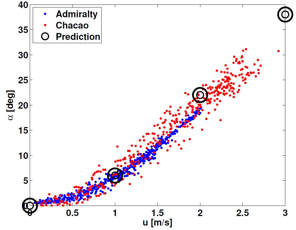
There are three primary mooring
examples included with the MD&D package [Example 1
(MOOR001.MAT), Example 2 (MOOR002.MAT), and Example 3
(MOOR003.MAT)], that can be loaded and evaluated to see the strengths and features of MD&D. MOOR002.MAT and MOOR003.MAT are similar, differing only in materials
and water depth (130m and 120m, respectively). Additionally, two mooring files (MOOR001TS.MAT and
MOOR002TS.MAT) have been saved with time dependent current vectors, so that movies or time dependent solutions can be sought and movies generated. Finally, I
have included two examples, one sub-surface and another a surface mooring, directly entered from Berteaux's (Cable Dynamics
and Mooring
Systems) software analysis package so that solutions obtained by MD&D
can be compared against CDMS's SFMOOR.EXE (Surface Mooring) and SSMOOR.EXE (Sub-Surface Mooring).
Shown to the right is a
plot from Jim Thomson of APL (Applied Physics Laboratory (APL) of the University of Washington, METS-2013), showing the measured mooring angles (blue and red dots), and predictions from MD&D for
two moorings deployed in Admiralty Inlet, where the currents reach 4-5 knots. At the higher speeds MD&D seems to very slightly over-predict the blow-down.
I would reduce the drag coefficients very slightly to achieve a better fit, but these predictions were done with no modifications to basic values available in MD&D.
 MOOR001.MAT (shown on the right) is a simple, sub-surface, Aanderaa current meter mooring. It
consists of 16 total elements, including a 37 inch ORE (Ocean Research Equipment Inc.) buoy, 80 m of
3/8 inch wire rope, a triple set of 16 inch Viny floats, an Aanderaa RCM-7 current meter (at a height
of 12.3 m off the bottom), 5 m of 3/8 inch wire rope, an EG&G 8242 acoustic release, 5 m of 1 inch
stud-link chain, a double railway wheel anchor, and miscellaneous shackles (fasteners) and a swivel.
Due to the crowding of labels, the fasteners and joiners are not listed when a mooring is plotted (as in the figure to the right), but are listed when the mooring elements
are displayed in the command window. The initial (no
current) height of the buoy (mooring) above the bottom is 95 m. This can be displayed by requesting
Display Mooring Elements from the Main Menu prior to requesting
a solution. The displayed information includes a list of the mooring element
number (from top to bottom), and mooring element names, their vertical "length", their buoyancy [kg],
and their height above the bottom. Not displayed are the horizontal (X and Y) displacements or wire
tensions and angles, since no formal calculations have been performed yet.
MOOR001.MAT (shown on the right) is a simple, sub-surface, Aanderaa current meter mooring. It
consists of 16 total elements, including a 37 inch ORE (Ocean Research Equipment Inc.) buoy, 80 m of
3/8 inch wire rope, a triple set of 16 inch Viny floats, an Aanderaa RCM-7 current meter (at a height
of 12.3 m off the bottom), 5 m of 3/8 inch wire rope, an EG&G 8242 acoustic release, 5 m of 1 inch
stud-link chain, a double railway wheel anchor, and miscellaneous shackles (fasteners) and a swivel.
Due to the crowding of labels, the fasteners and joiners are not listed when a mooring is plotted (as in the figure to the right), but are listed when the mooring elements
are displayed in the command window. The initial (no
current) height of the buoy (mooring) above the bottom is 95 m. This can be displayed by requesting
Display Mooring Elements from the Main Menu prior to requesting
a solution. The displayed information includes a list of the mooring element
number (from top to bottom), and mooring element names, their vertical "length", their buoyancy [kg],
and their height above the bottom. Not displayed are the horizontal (X and Y) displacements or wire
tensions and angles, since no formal calculations have been performed yet.
 When MOOR001.MAT is loaded, a preset current profile (environmental condition) is loaded, specifying a
water column 120 m deep, with surface current of 2 ms-1. When evaluated, this strong current causes the mooring to lay over considerably. Shown to
the left is the plot of the mooring forced with a single component current of 2 ms-1. The
major mooring components (i.e. floats, current meters, acoustic releases,.. are plotted as special
symbols on the mooring wire. Shown below is the information displayed in the command window
subsequent to the evaluation and after requesting the updated display.
When MOOR001.MAT is loaded, a preset current profile (environmental condition) is loaded, specifying a
water column 120 m deep, with surface current of 2 ms-1. When evaluated, this strong current causes the mooring to lay over considerably. Shown to
the left is the plot of the mooring forced with a single component current of 2 ms-1. The
major mooring components (i.e. floats, current meters, acoustic releases,.. are plotted as special
symbols on the mooring wire. Shown below is the information displayed in the command window
subsequent to the evaluation and after requesting the updated display.
As part of the "solution", information with regard to the tensions and recommended
anchor mass is displayed. Total tension on the anchor, as well as the vertical and horizontal
components of tension are displayed. The height of the buoy is now 88.99 m, with a horizontal
displacement in the X direction (associated with a U [eastward] current) or 31.4 m. The 37 inch ORE
buoy provides a buoyant force equivalent to 300 kg, but due to the drag on the buoy, the tension in
the wire just below the buoy is 305.9 kg. Since the 3/8 inch wire has negative buoyancy (sinks), at
the bottom of the 80 m length of wire, the tension is reduced to 293.8 kg. The angle from vertical
for the first section of wire changes from 11.5 degrees just below the buoy to 23.4 degrees just
above the triple Viny floats. The Viny floats are now at a height of 12.06 m, down from the
no-current case of 13.9 m. The height of the Aanderaa current meter is 11.0 m and the acoustic
release is at 5.31 m above the bottom. The inclusion of mid-mooring floatation increases the tension
for elements below the Viny floats. The 1 inch chain is heavy (buoyancy of -13 kg/m) and
significantly reduces the tension at the anchor (242.6 kg).
Below is the solution for moor001.mat as displayed in the
Matlab® command window.
Return to Examples
Return to The Main Menu
Return to Users Guide TOC
MOOR002.MAT (shown on the right) is another simple mooring, now configured to represent an
S-shaped surface mooring. It consists of 19 components, with a single Aanderaa current meter near the
bottom, and three sets of floatation separated by 3/8 inch wire rope. The mooring height (without
currents) is 136.63 m. The water depth is set in the prescribed current profile to 130 m. Example 3 is a similar mooring, but the upper section of 3/8 wire has been replaced
with polypropylene rope, and the water depth has been reduced to 120 m. The "S" shape is derived from
the fact that during weak current conditions, the upper "wire" will hang down, with the lower portion
of the mooring being supported by the second set of floats, and the upper most floatation device will
then only support the weight of the top section of wire.
When a solution is sought for moor002.mat, since the height of the initial mooring
exceeds the water depth, the command window indicates the program knows it may be searching for a
"surface" solution (see displayed solution below). The default current profile in moor002.mat
includes both U and V, with peak current speeds at the surface of 0.5 and 0.45 m/s, respectively. In
searching for a converged "surface" solution, the algorithm must determine the exact amount of
buoyancy required to support the mooring under the tensions introduced by the submerged weight of the
mooring components and the drag on the submerged components. By definition, a "surface" solution will
not "use" all of the buoyancy of the top floatation device, leaving a portion of the floatation above
water. This reduces both the effective (used) buoyancy of the top floatation device, and the drag of
the float, proportional to the portion in the water. Consequently, a "surface" solution may take many
more iterations to converge. For the case of moor002.mat, 28 iterations are needed before a converged
surface solution is reached (a dot is displayed for each iteration).
 Shown here is the plot of the solution for moor002.mat. The normalized current profiles are plotted,
normalized in such a way as to give full scale to the maximum speed for each component (U and V),
with this maximum speed plotted at the top of the velocity profile. We can see the lifting of the
mooring by the upper two floatation devices and the displacement of the mooring in both the X and Y
directions. Below is the text display of the solution, showing the fact that it is a surface
solution, using only 14% of the surface float to support the top section of wire.
Shown here is the plot of the solution for moor002.mat. The normalized current profiles are plotted,
normalized in such a way as to give full scale to the maximum speed for each component (U and V),
with this maximum speed plotted at the top of the velocity profile. We can see the lifting of the
mooring by the upper two floatation devices and the displacement of the mooring in both the X and Y
directions. Below is the text display of the solution, showing the fact that it is a surface
solution, using only 14% of the surface float to support the top section of wire.
Two very important "features" of MD&D can be
demonstrated with the mooring stored in MOOR002.MAT. First, if the current profiles are modified
such that the depth of the water [height of the first current estimate z(1)] is reduced to 95 m, and
a solution is then requested, we find that the second set of floats is now on the surface, and the
upper most floatation and wire will hang downstream of this second set of floats and provide
no vertical tension, only horizontal drag. This type of solution is extremely tricky to get to
converge, and so the upper portions of the mooring (above the second set of floats), where there are
no instruments, is "removed" in order to find a solution. A message stating that several components
of the mooring have been removed is displayed in the command window, and the remaining portion of the
mooring is then used to find a solution. This limitation means that an "S-shaped" mooring where the
second set of floatation device(s) can fully support the mooring as a surface solution can NOT
be evaluated (with out removing the "S" portion of the string). Another "feature" can be tested by
taking the original MOOR002.MAT mooring and increasing the upper most (surface) current speed. If one
sets U(1) to 1.5 m/s at z(1)=130 (using Set/Load Environmental Conditions), then
while the solution is sought, the model will find that 100% of the upper most float is required to
support the mooring, and the solution becomes a sub-surface solution. Note for this modified example,
the large double railway wheel anchor is only just sufficient. When such a mooring is forced by time
varying currents (i.e. MOOR002TS.mat), one can determine when a surface mooring will become a
sub-surface mooring. This is particularly important as the original anchor mass maybe sufficient for
a surface solution, but inadequate for a sub-surface solution.
Solution for MOOR002.MAT
Return to Examples
Return to The Main Menu
Return to Users Guide TOC
 The mooring example found in file MOOR003.MAT is virtually identical to that of MOOR002.MAT, except
that the top section of 3/8 inch steel wire has been replaced with 40 metres of 3/4 inch
Polypropylene, and the water depth (current profiles) has been reduced to 120 m. Since Polypropylene
is positively buoyant (floats), the "S" characteristics of the mooring change somewhat. For weak
current conditions and water depths shallower than the full mooring height, a portion of the
Polypropylene rope will lie on the surface, with the surface float streaming off down current of the
mooring (see solution plot to the left). The top float is only supporting itself and providing slight
horizontal drag (proportional to the fraction of the float that is submerged). Since there is no wave
action in this model, the top float sits passively on the surface. In rough seas, one may expect the
float to "bob" and have an increased (albeit periodic) net drag. If one modifies the current profile
data loaded from MOOR003.MAT, and increases the surface current speed, then the mooring (MOOR003.MAT)
will gradually stretch out and begin to use the top float for buoyancy. Alternately, one can test a
time dependent solution by loading the time dependent currents found in file
VELTS.MAT, and follow the steps to Make a Movie. The time dependent solution
will have periods of slack water with a surface float and slack Polypropylene, extended surface "S"
solutions, and submerged solutions, as the currents go through a simple four quadrant "tidal"
oscillation.
The mooring example found in file MOOR003.MAT is virtually identical to that of MOOR002.MAT, except
that the top section of 3/8 inch steel wire has been replaced with 40 metres of 3/4 inch
Polypropylene, and the water depth (current profiles) has been reduced to 120 m. Since Polypropylene
is positively buoyant (floats), the "S" characteristics of the mooring change somewhat. For weak
current conditions and water depths shallower than the full mooring height, a portion of the
Polypropylene rope will lie on the surface, with the surface float streaming off down current of the
mooring (see solution plot to the left). The top float is only supporting itself and providing slight
horizontal drag (proportional to the fraction of the float that is submerged). Since there is no wave
action in this model, the top float sits passively on the surface. In rough seas, one may expect the
float to "bob" and have an increased (albeit periodic) net drag. If one modifies the current profile
data loaded from MOOR003.MAT, and increases the surface current speed, then the mooring (MOOR003.MAT)
will gradually stretch out and begin to use the top float for buoyancy. Alternately, one can test a
time dependent solution by loading the time dependent currents found in file
VELTS.MAT, and follow the steps to Make a Movie. The time dependent solution
will have periods of slack water with a surface float and slack Polypropylene, extended surface "S"
solutions, and submerged solutions, as the currents go through a simple four quadrant "tidal"
oscillation.
Return to Examples
Return to The Main Menu
Return to Users Guide TOC

 The next example (file
cdmsum1.mat) was taken directly from the Cable Dynamics and Mooring Systems™ (CDMS) Users
Manual for the program SSMoor.exe (sub-surface mooring), and was used for model verification. The
mooring, shown on the right, consists of a large (1.2m ) diameter spherical floatation device located
483 m above an anchor (SSMoor.exe and SFMoor.exe do not include the anchor in their list of mooring
hardware). Three "vanilla" current meters, coded into the database as "CDMS CM", are strung between
wire and kevlar segments. A set of 10 17 inch Benthos glass floats are strung at the bottom, along with
an acoustic release ("CDMS AR") and some 3/8 inch chain above the anchor. Strings of ten paired 17 inch
benthos glass floats are commonly used by the mooring group at the Woods Hole Oceanographic Institute.
The example described in the CDMS Users Manual is for a single component current profile (which is all
that is allowed in SSMoor.exe), with a water depth of 525 m and a surface current of 1.5 m/s. The
solution is plotted on the left, showing the effective height of 432 m and a horizontal displacement of
75 m. The total tension at the anchor is 827 kg, with 816 kg of vertical lift and 131 kg of horizontal
drag. This agrees very well with the numbers generated by SSMoor.exe. Shown below is the
Matlab®
command window data, displaying the current and density profiles used, and the solution, including the
suggested anchor requirements and the segment by segment tensions and positions. This is followed by
the solution generated using SSMoor.exe. The agreement is good (to get heights: water depth - component
depth, e.g. 525 - 92.6=432.4), but there are subtle differences. These differences are attributed to
the formulae used to calculate drag, SSMoor using Ui*Ui while MD&D uses |U|*Ui, where the subscript "i" refers the component
of the current in the direction of the drag force, with MD&D forces
always being slightly higher.
The next example (file
cdmsum1.mat) was taken directly from the Cable Dynamics and Mooring Systems™ (CDMS) Users
Manual for the program SSMoor.exe (sub-surface mooring), and was used for model verification. The
mooring, shown on the right, consists of a large (1.2m ) diameter spherical floatation device located
483 m above an anchor (SSMoor.exe and SFMoor.exe do not include the anchor in their list of mooring
hardware). Three "vanilla" current meters, coded into the database as "CDMS CM", are strung between
wire and kevlar segments. A set of 10 17 inch Benthos glass floats are strung at the bottom, along with
an acoustic release ("CDMS AR") and some 3/8 inch chain above the anchor. Strings of ten paired 17 inch
benthos glass floats are commonly used by the mooring group at the Woods Hole Oceanographic Institute.
The example described in the CDMS Users Manual is for a single component current profile (which is all
that is allowed in SSMoor.exe), with a water depth of 525 m and a surface current of 1.5 m/s. The
solution is plotted on the left, showing the effective height of 432 m and a horizontal displacement of
75 m. The total tension at the anchor is 827 kg, with 816 kg of vertical lift and 131 kg of horizontal
drag. This agrees very well with the numbers generated by SSMoor.exe. Shown below is the
Matlab®
command window data, displaying the current and density profiles used, and the solution, including the
suggested anchor requirements and the segment by segment tensions and positions. This is followed by
the solution generated using SSMoor.exe. The agreement is good (to get heights: water depth - component
depth, e.g. 525 - 92.6=432.4), but there are subtle differences. These differences are attributed to
the formulae used to calculate drag, SSMoor using Ui*Ui while MD&D uses |U|*Ui, where the subscript "i" refers the component
of the current in the direction of the drag force, with MD&D forces
always being slightly higher.
MD&D Solution for CDMS-1 (cdmsum1.mat)
SSMoor Solution for CDMS-1
The above tables show how similar the solutions are. Compare for example the tension
in the wire underneath the float. Due to differences in how the hydrodynamic drag is calculated, the
tension above the anchor is predicted to be slightly (2%) higher by MD&D than by SSMoor. When the zero current solutions are sought, the
positions and tensions are identical. Fortunately, the difference in solutions with currents
errs (if MD&D is in error, although I believe it is not) on the side of
requesting a larger anchor
mass and slightly higher in-line tensions. Similarly, the component positions are in good agreement.
SSMoor.exe displays the depth of the devices, while I have chosen to display the height above
the bottom. To get height above the bottom, subtract the SSMoor.exe's component depth from
the water depth (525m). So SSMOOR predicts a height of 525-92.6=432.4m,
whereas MD&D has the height of the top of the buoy at 432.07 + 0.6 = 432.67m, or a 27cm difference (0.06% difference).
Return to Examples
Return to The Main Menu
Return to Users Guide TOC
 The last example (file cdmsum2.mat) is the surface float mooring example presented
in the CDMS Users Manual for the Surface Mooring program SFMoor.exe. This mooring is similar to
that of CDMS-1, but includes a long segment of nylon rope, which has good
stretch and strength characteristics. The total length of the mooring components is 1950m, and the
mooring is deployed in 2000 m of water. A 3D current structure is imposed, with all U, V and W
specified. The surface float is a 2m diameter sphere, and current meters are located at the surface
and at a depth of 950 m. The Nylon rope stretches under the tension, so that 52% of the float is
used to support the surface mooring. For demonstration purposes, the mooring configured in the MD&D file cdmsum2.mat, has only a single railway wheel as the
anchor, clearly insufficient for a large, current forced surface mooring. When the solution is
sought, the tension on the anchor is estimated, and a warning is posted to indicate that the selected
anchor is most likely insufficient for this mooring. A six railway wheel anchor would work.
The last example (file cdmsum2.mat) is the surface float mooring example presented
in the CDMS Users Manual for the Surface Mooring program SFMoor.exe. This mooring is similar to
that of CDMS-1, but includes a long segment of nylon rope, which has good
stretch and strength characteristics. The total length of the mooring components is 1950m, and the
mooring is deployed in 2000 m of water. A 3D current structure is imposed, with all U, V and W
specified. The surface float is a 2m diameter sphere, and current meters are located at the surface
and at a depth of 950 m. The Nylon rope stretches under the tension, so that 52% of the float is
used to support the surface mooring. For demonstration purposes, the mooring configured in the MD&D file cdmsum2.mat, has only a single railway wheel as the
anchor, clearly insufficient for a large, current forced surface mooring. When the solution is
sought, the tension on the anchor is estimated, and a warning is posted to indicate that the selected
anchor is most likely insufficient for this mooring. A six railway wheel anchor would work. 
A comparison of the wire tensions and component positions as predicted by MD&D and SFMoor.exe are shown below in the two following tables.
MD&D Solution for CDMS-2 (cdmsum2.mat)
SFMoor Solution for CDMS-2
These tables show how similar the solutions are, in both wire tension and angle, and
component
position. Slight differences are attributable to how MD&D correctly
calculates
hydrodynamic drag. When the zero current solutions are sought, the positions and tensions are
identical.
Return to Examples
Return to The Main Menu
Return to Users Guide TOC
The user of this package takes full
responsibility for designing and building safe and reliable moorings and towed bodies, that facilitate
safe and easy deployment, and safe and easy recovery.
This set of programs is only an aide in evaluating different
mooring designs and configurations forced by varying 3D currents. It does not attempt to estimate the
forces and tensions during lifting, deployment, or recovery, which may be significantly higher than the
"in-water/static" tensions, as components hanging out of water will have significantly more weight
and "falling" moorings will experience significant velocities and drag. The author does not endorse or provide
sources for instruments or mooring components (i.e. wire or chain), nor do I verify the manufacturers specified
strength and tension limits. If in doubt, add a safety factor of 1.5, or larger.
Having said that, I do recommend that all mooring fasteners and connectors be "rated".
The more expensive/better suppliers (i.e. Crosby) certify and rate their gear. Cheap, no-name shackles should be avoided at all times.
The Canadian Coast Guard will not allow any mooring onboard not built with certified components.
"Knots" should be avoided, and proper terminations (splices with thumbles) should be prepared by skilled professionals.
I have had moorings part (while I gained experience), it is always at the weakest link
and was usually where I had used a less-than top quality component.
Similarly, caution when using any "used" components, including wire and rope. Careful inspection of all components is time well spent.
After rope has been under tension, it will no longer meet the original load or breaking specification.
Never stand in or walk under a "bight", or under any heavy component lifted off the deck of a ship.
Remove all non-essential participants/personnel from the work area when deploying or recovering a mooring.
This package can be used to predict wire tensions, anchor weights, and sensor
heights, potentially for backing out the actual depth/height of a mooring sensor in a current and
correcting for mooring motion. My intent is to maintain this package as a free research tool.
However, the potential uses are varied, including commercial applications. If you use this package
and find it helpful, appropriate reference to this
article or the Mooring Design and Dynamics web
page is appreciated.
Return to The Main Menu
Return to
Users Guide TOC
- Berteaux, H. O., 1976: Buoy Engineering,
John Wiley & Sons, New York.
- Myers, J.J., C.H.Holm, and R.F.McAllister,
1969:Handbook of Ocean and Underwater Engineering, McGraw-Hill, New York.
- Schlichting, H., 1968. Boundary Layer Theory. McGraw-Hill, New
York.
- Hoerner, S.F., 1965: Fluid-Dynamic Drag, Published by Author.
- Dewey, R.K., 1999,
Mooring Design & Dynamics - A Matlab Package For Designing and Analyzing Oceanographic Moorings,
Marine Models Online, Vol(1), pp 103-157.
- Thomson, J., L. Kilcher, M. Richmond, J. Talbert, A. deKlerk, B. Polagye, M. Guerra, and R. Cienfuegos, "Tidal turbulence spectra from a compliant mooring," Proc., 1st Marine Energy Technology Symposium, METS2013, 10-11 April, Washington, D.C., 2013.
Return to The Main Menu
Return to Users Guide TOC
This paper was first published in Elsevier
Marine Models Online, Vol(1), pp 103-157.
You are visitor 51064 since March 1999.
Last modified: February 6, 2024.
Questions and comments are welcome,
Richard Dewey