Mooring Design &
Dynamics
A Matlab Package for Designing and Testing
Oceanographic Moorings And Towed Bodies
by
Richard K. Dewey,
University of Victoria
RDewey@UVic.ca
Latest Version is 2.7, November 2024 (update)
V2.2 was a MAJOR RELEASE. The entire form and lift drag force formulae for moorings and towed bodies have been re-written.
V2.6 fixes an essential bug for large surface float moorings introduced in v2.5.
V2.7 fixes a bug in the lift drag term for a towed body.
Also Checkout The Users Guide
Mooring Design and
Dynamics is a set of
MATLAB routines to
assist in the design and evaluation of single point oceanographic moorings, mooring data,
and towed body apparatus. Both
surface (including "S" moorings) and sub-surface moorings can be designed and evaluated using a
set of graphic user interfaces and a preliminary database of components. The package allows the user
to design and evaluate the dynamics of oceanographic moorings under the influence of time dependent
(slowly varrying) 3 dimensional currents by solving a set of static force balance equations in order to determine
the tension and spatial position of each mooring element relative to the anchor.
Once a mooring has been constructed using
the MD&D set of programs, the position of each mooring element within a time dependent 3 dimensional
sheared current [i.e. U(z,t), V(z,t), and W(z,t)] is calculated by solving for the balance of forces
acting on it. The towed body problem is also included, such that the depth and wire lengths for specific tow
configureations can be predicted. Mooring and Towed Body elements may include current meters, in-
line floats, thermistor chains,
acoustic releases, etc., each with a specified weight(buoyancy), shape, and effective fluid dynamic drag.
The component information is saved within an easily accessible database to aid in the rapid design and
reconfiguration of moorings and towed bodies. Wire, rope, and chain segments are divided
into multiple "hinged" pieces, so that the shape of the mooring and towed line will realistically represent a
sub-surface, surface mooring, or towed body under the influence of a sheared currents. For the Towed body
problem, both the currents and ship velocity can be set for complex cross flow operations.
Note: The programs do NOT consider rapid (high frequency) dynamics associated with waves and other forces which would
result in continuous motions of the mooring compoents. As such, the formulation does not include inertial or
acceleration affects, including snap loading. The solutions obtained by MD&D are "static", in that the forces
(drag, buoyancy, lift, etc.) are all in equalibrium. The "dynamics" considered by MD&D are quasi-stationary,
in that you can simulate a series of static solutions for a slowly (5 minute) varrying
ocean current, even producing a movie annimation (or record) of the mooring postitions over time (hours to days).
I used this feature to correct the sensor depth of a thermistor string by removing simulated mooring displacements
for each sensor along the mooring line.
Wave and mooring vibrations are real and do exist, and if information about such dyanmics is desired, then
another program is required. Also, the complex forces during mooring deployment and recovery are not esitamted,
including snap-loading, when tensions in a mooring line go from very small values (slack) to full on, often exceeding
the mass of the mooring components, when inertaial forces can be extreme. Snap loads can exceed 4-7 times the
static mass wright of a system, so these forces are extremely dangerous and often result in failed mooring or towed body systems.
The Users Guide [now published in
Marine Models Online
, Vol(1), pp 103-157], describes the features and capabilities of the programs, and can be
downloaded in either HTML or PDF fotmats.
The Users Guide and programs are posted on the
web as zipped/compressed files accessable from
MD&D Download Page.
The HTML Users Guide can be installed locally to provide
on-line help (from within MATLAB) to the many features and capabilities included in MD&D. If
installed into /matlab/help/local/mdd/* it can be accessed from the MATLAB command prompt by typing
"mdd".
The programs are written to use MATLAB's graphic user interface capabilities,
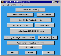
 with pull down
menus (i.e. see the figure to the left) and easy access to a mooring element database
and the built-in features and strengths of MATLAB (i.e. 3D plot manipulations). Once a
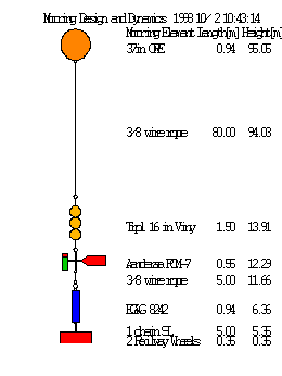
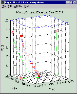
mooring has been designed (built), it can be evaluated and plotted (see the figure to
the right). I have included "joiners", such as shackles, so that the mooring list
represents a complete list of the mooring components, and can be used to determine the
parts list for the mooring. The user can specify static current, wind and density
fields, or load time dependent currents and density profiles to see how the mooring
will respond to varying environmental conditions (wave action is not considered). A
movie of the mooring motion can be generated for time dependent currents, or the
vectors of time dependent mooring element positions can be saved for post processing
and mooring motion correction. For surface moorings, the program will allow the
mooring to become a sub-surface mooring if the currents are sufficiently strong.
Therefore, the necessary buoyancy, wire tensions, and anchor weights can be evaluated
under the most stringent and varied conditions anticipated. The mooring can easily be
re-designed to maintain a specified depth, level of safety, or shape if necessary.
The Solution
The code for the dynamics (MOORDYN.M and TOWDYN.M) solve for the positions of each mooring and towed body
 element iteratively until the positions converge, usually only a few iterations are
required for sub-surface, weakly sheared configurations. In a strongly sheared current and for
surface moorings, as many as 100 iterations may be required. Mooring element positions
are solved to within 1 cm in the vertical! The first pass (solution) starts with the
mooring standing vertically in the water column. The water depth is set by the current
profile. For subsurface moorings, it is assumed that the velocity data is sufficient
to describe the currents throughout the water column, from the bottom (z=0) to a
height that exceeds the vertical height of the mooring. For surface moorings, the top
(highest) velocity value defines the water depth. A density profile, and even a time
dependent density profile may be entered, as the drag depends (2%) on the water
density. A constant wind can be set that produces an additional 2% surface current in
the direction of the wind (modify the wind direction if you want to simulate Ekman
drift), which decreases linearly to a depth that increases with wind speed. The model
will predict if the surface float gets "dragged" under the surface by the currents.
Once the first estimate of the "tilted" mooring has been made, new solutions are
sought with the new positions of each element in the sheared current used to
re-calculate the drag, considering "tilted" elements and appropriate drags. Also, now
that the wire/rope are under tension, there may be stretching. The database assumes
six different rope materials may be used (i.e. Steel, Nylon, Dacron, Polypropylene,
Polyethylene, Dyneema, and Kevlar), for which appropriate moduli of elasticity are used. If the
position of the top element (float) moves less than 1 cm (!) between iterations, then
it is assumed the solution has converged and the position of the mooring has been
found. Inertia is not considered, in that the solutions, even the time dependent ones
are all assumed to be (locally) "static". In strongly sheared currents, where small
differences in element depth may result in significant changes in the drag, and for
surface float moorings, where the exact percentage of the required surface floatation
needs to be determined, it may take many (100) iterations to converge. On a Pentium
133MHz, this may take a few seconds. Once converged, the mooring is plotted, and the
final element positions, wire tensions, lengths and angles can be printed.
The solution assumes that each mooring element has a static force balance in each
direction (x, y, and z), and that between solutions the mooring has time to adjust. No
inertial affects are considered. The forces acting in the vertical direction are: 1)
Buoyancy [mass times g] positive upwards (i.e. floatation), negative
downwards (i.e. an anchor), 2) Tension from above [Newtons], 3)
Tension from below, and 4) Drag from any vertical
velocity. In each horizontal direction, the balance of forces is simply: 1) Angled
Tension from above, 2) Angled Tension from below,
and 3) Drag from the horizontal velocity. I do not calculate "lift".
The net buoyancy is determined by the mass and displacement of the element and is
constant. In MOORDESIGN.M the buoyancy is entered in [kg, positive upwards], and
converted into a force in MOORDYN.M. The drag is determined for each element according
to the shape, the exposed surface area of the element to the appropriate velocity
component, and a drag coefficient (see below). Only cylinders and spherical shapes are
assumed. More complicated shapes can always be approximated by either a cylinder or a
sphere with an appropriate (adjusted) surface areas and drag coefficients. Spheres
characterize devices whose surface area is isotropic, while cylinders are anisotropic
with respect to vertical and horizontal directions. Vained devices are "modelled" as
cylinders with appropriate surface areas and drag coefficient.
For each element there are three equations and six unknowns (tension from above,
tension from below, and the spherical coordinate angles the tensions make from the
vertical (z) axis (psi) and in the x-y plane (theta). However, the top element has no
tension from above and therefore, three unknowns and three equations. The tension and
appropriate tension angles between any two elements is equal and acts in opposite
directions, so that the tension from above for the lower element is equal and opposite
to the tension and angles from below for the upper element. The method of solution is
to estimate the lower tension and angles for the top element (floatation), and then
subsequently estimate the tension and angles below each subsequent element. The
resulting set of angles [psi(z) and theta(z)] and element lengths determines the exact
(X, Y, Z) position of each mooring element relative to the anchor. Also, once the top
of the anchor is reached, one has a direct estimate of the necessary tension required
to "anchor" the mooring. This tension can then be inverted into an estimate of the
required anchor weight. A Wood Hole (WHIO) safety factor is used to estimate a safe,
realistic anchor weight.
Specifically, the solution is obtained as follows. First the velocity (current) and
density profiles and wire/chain sections are interpolated to approximately one metre
vertical resolution using linear interpolation. Then the drag on each mooring element
in a vertical orientation is calculated by,

where Qjis the drag in [N] on an
element in water of density rhow in the direction j (x, y, or z),
Uj is the velocity component at the depth of the mooring element
with a drag coefficient CD appropriate for the shape of the
element, with surface area A perpendicular to the direction j. U is
the total vector magnitude of the velocity,

at the depth of the element. The drag in all three
directions is estimated, even the vertical component which in most flows is likely to
be very small.
Once the buoyancy and drag for each mooring element, and each segment of mooring
wire and chain have been calculated, then the tension and the vertical angles
necessary to hold that element in place (in the current) can be estimated. The three
[x,y,z] component equations to be solved at each element are:

where
Ti is the magnitude of the wire tension from above, making
spherical angles psii and thetai from the
vertical and in the x and y plane, respectively, Bi is the
buoyancy of the present element, g is the acceleration due to gravity (=9.81
ms-2), and Qxi, Qyi and
Qzi are the respective drag forces. The tension below this element
is Ti+1, with spherical coordinate angles
psii+1 and thetai+1. Thus each element acts
dynamically as a "hinge" in the mooring, although it may be "rigid" in reality.
Once all of the angles have been calculated, the position of each element can be
calculated using the length of each element, stored in array H(1,:) in MOORDESIGN.M
and MOORDYN.M, namely
 .
.
The tilt of each element is taken into account when estimating the drag and surface
area (1). In particular, the drag on a spheres require no direct modification except
that the actual velocity acting on it corresponds to the velocity at the depth of the
"tilted" mooring. For cylinder elements, once the mooring is tilting over, several
modifications occur. First, the exposed area in the horizontal and vertical directions
change. Also, the drag is broken into tangential and normal components for each
current direction acting on the element. This holds for wire/rope/chain as well (which
are treated as cylinder segments), with tilted wire having both a reduced area and
drag coefficient to a horizontal current, but increased exposure and drag in the
vertical.
Towed Body Solution
Version 2.0 (April 2000) of MD&D now includes the routines necessary to solve for the towed body
solution. Three main configureations are possible: 1) Simple bodies can be suspended from
a single wire and evaluated for depth, position, line tension, and line length from a
moving ship in a sheared current, 2) bodies can be suspended with sink-weights along the
tow line, or 3) bodies can be towed with a surface float/spacer extending behind the ship.
For the towed body case, the wire length can be specified, or a desired depth can be
saught. Cross currents and lateral position is also evaluated when cross currents are
specified, as might be recorded by a hull mounted ADCP.
Time Varying Currents
The MATLAB routine MOORDYN.M can be used to "model" the mooring motion for a time
dependent current. The latest version allows you to "model" the mooring under the
influence of time varying currents (i.e. a time series recorded by an Acoustic Doppler
Current Profiler), generating a MATLAB movie and vectors of the position and tension
histories for each mooring element. The movies can be saved and viewed again later
using the "load movie" capabilities built into Mooring Design and Dynamics. The
present code does not estimate high frequency mooring motion, such as vibrations or
strumming, although such calculations are possible given the Strouhal number 0.21=
fd/U, where f is the frequency of vibration, d is the diameter of the
cylinder element or wire, and U is the total speed past the
device/wire.
Chain and Shackle Specifications
I have added a few scanned images of various Chain and
Shackle Specifications. These pages are direct scans from Myers, Holm and
McAllister's "Handbook of Ocean and Underwater Engineering" (McGraw-Hill). They
include the dimensions, weights, and strength specifications for various sizes and
types of chains and shackles. The data are all in inches and pounds, but can easily be
converted to metric. I did not add all of these to the database for display reasons,
but the data for your most common mooring components can easily be added to the
database for future and easy use in designing moorings.
Feedback
If you find a bug/feature, please check that you have the latest version (and file
date, since I make small improvements without a version increment!). Please report any
real errors/bugs or suggested improvements for this package to RDewey@uvic.ca I am particularly interested if you
have mooring data (pressure records) that can be simulated and compared against model
output. I originally tested the package under MATLAB
5.3 on Windows 95, 98, NT, and HP-UNIX. I think it still works in all versions of Matlab (2023).
See and READ the published Users Guide
describing this package, it's use, and the solutions it provides.
You are visitor 13138 since 1/12/98.

 with pull down
menus (i.e. see the figure to the left) and easy access to a mooring element database
and the built-in features and strengths of MATLAB (i.e. 3D plot manipulations). Once a
mooring has been designed (built), it can be evaluated and plotted (see the figure to
the right). I have included "joiners", such as shackles, so that the mooring list
represents a complete list of the mooring components, and can be used to determine the
parts list for the mooring. The user can specify static current, wind and density
fields, or load time dependent currents and density profiles to see how the mooring
will respond to varying environmental conditions (wave action is not considered). A
movie of the mooring motion can be generated for time dependent currents, or the
vectors of time dependent mooring element positions can be saved for post processing
and mooring motion correction. For surface moorings, the program will allow the
mooring to become a sub-surface mooring if the currents are sufficiently strong.
Therefore, the necessary buoyancy, wire tensions, and anchor weights can be evaluated
under the most stringent and varied conditions anticipated. The mooring can easily be
re-designed to maintain a specified depth, level of safety, or shape if necessary.


 .
.