
Open source gears for illustrations
contact | home | lab | links | opportunities | people | publications | research |Introduction
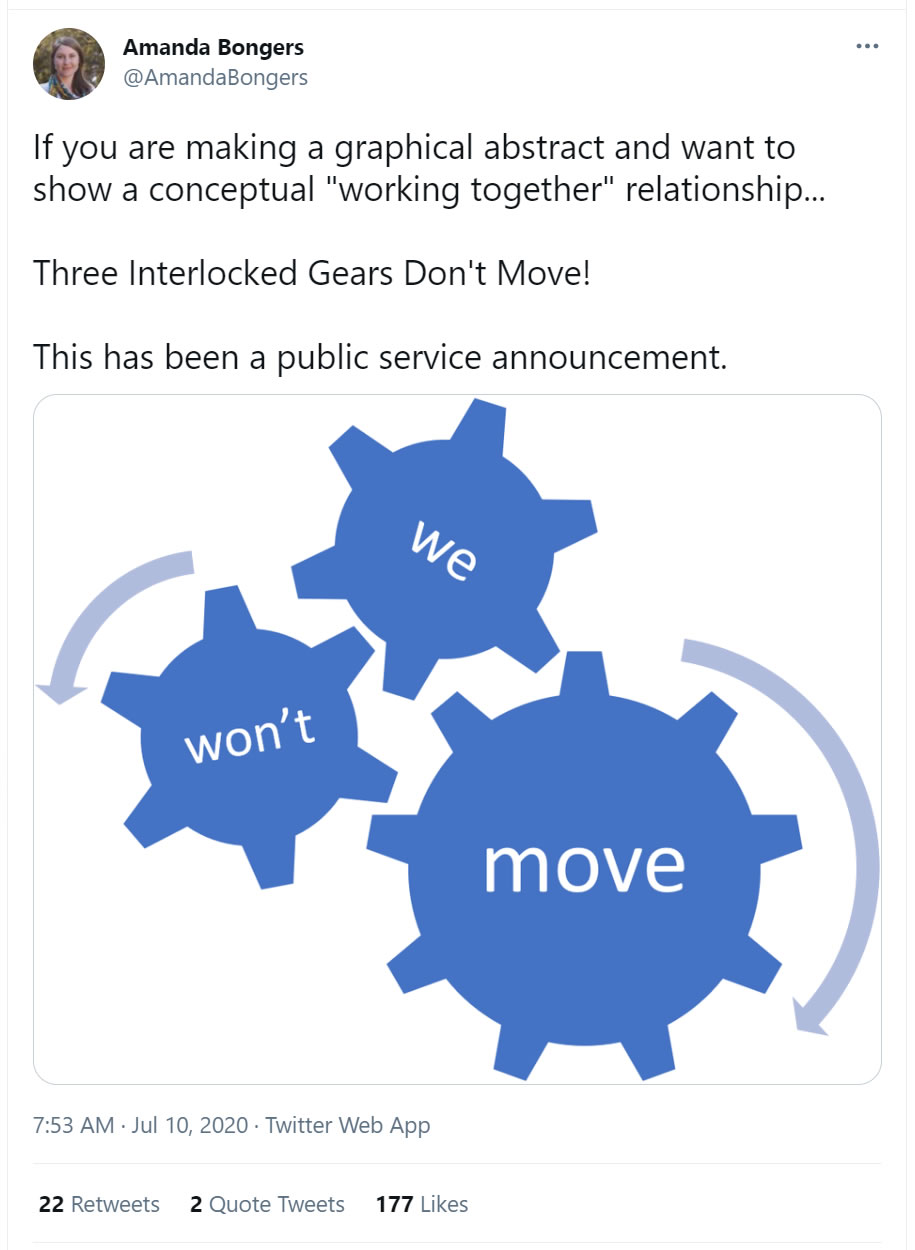
Gears are a common visual metaphor for interconnected systems in the sciences. However, they are often represented inaccurately, with graphical abstracts replete with examples that involve gears that don’t mesh properly, or are of different tooth sizes, or are connected in such a way that the assembly can’t possibly move. One of these problems was highlighted in a 2020 tweet by Amanda Bongers:
Drawing gears is something of a specialist subject and therefore there is a lack of readily available resources, apart from clipart in some programs. This preprint is designed to alleviate that need; spur gears with a wide range of tooth counts (5-15, 18, 20, 25, 30) are provided in a range of formats, suitable for researchers to easily incorporate into their drawing programs. Gears with >13 teeth are also available in spoked form. All gears were drawn using Mathias Wandel’s Gear Template Generator.
(if you find these resources useful, I'd love to see the images you make! Please share by email or @mcindoe)
Making 2D images
Options provided for CorelDraw (.cdr), Adobe Illustrator (.ai), and any program that handles vector graphics (.svg).
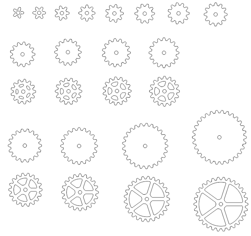
gearoutlines.cdr, gearoutlines.ai, gearoutlines.svg
If you have no drawing programs that you are familiar with, the powerpoint (.pptx) file provided contains all the gear images (embedded as .emf files).
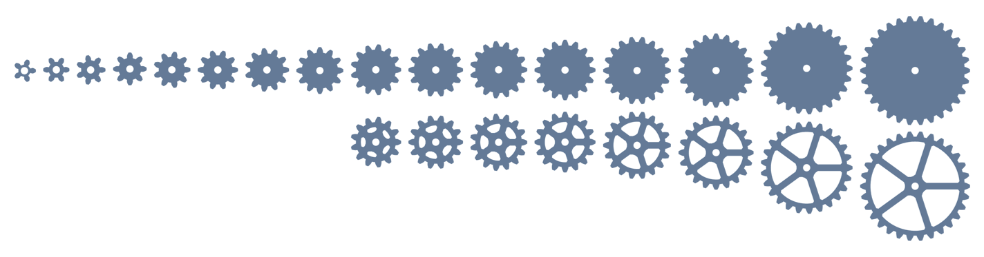
These can be colored by clicking on the gear in question and using Picture Tools > Color. Modifying the choice of colors can be done via Design > Variants > Colors > Customize Colors (also reachable by typing “color” into the help box). Select the colors for the gears there. These gears can be pasted into other programs, such as ChemDraw.
Making 3D images
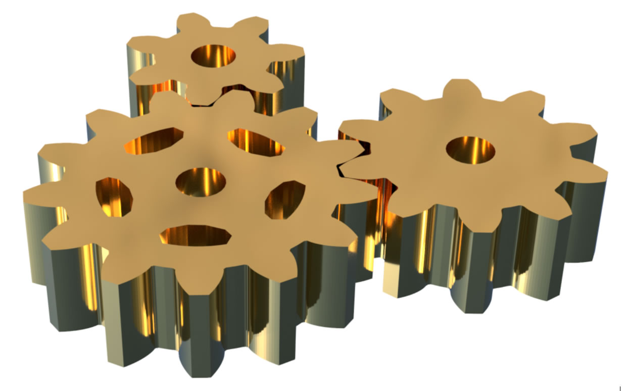
The .stl files provided below (right-click to save files) can be imported into whatever 3D modelling program you prefer to use.
5, 6, 7, 8, 9, 10, 11, 12, 13, 13s, 14, 14s, 15, 15s, 18, 18s, 20, 20s, 25, 25s, 30, 30s
The naming is by number of teeth; an “s” indicates that gear is spoked (only available for tooth counts 13 and higher). There are lots of choices - a simple and effective 3D modelling program is Paint 3D, provided freely with all Windows computers. Align your gears in the 2D view, then switch to 3D view and rotate freely using the right mouse button. Fast and effective, and easy to color and apply metallic finishes. The image below was rendered using Fusion360 (free to academic users) in brass.
Rules for construction
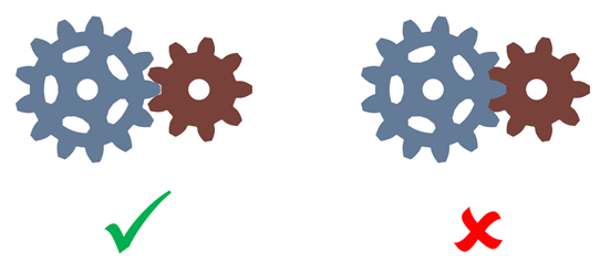
1. Scaling the gears is fine, but they should all be scaled by the same amount.
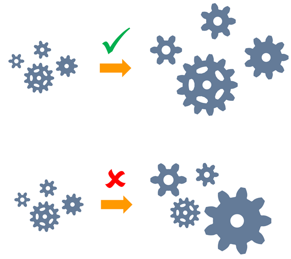
2. Teeth should mesh such that they are just touching. Better to leave a slight gap rather than overlap.
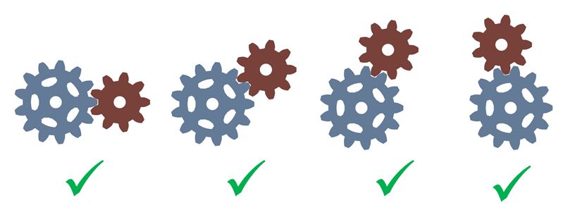
3. Don’t worry about rotating the gears (except for aesthetics) – provided they’re just touching at two points, they are a functional pair.
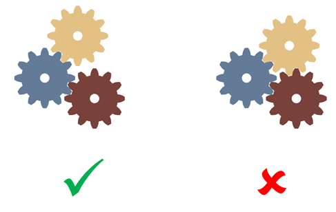
4. Don’t lock gears such that they can’t actually turn. Consider the mechanics of the gears during assembly.
© JS McIndoe, Department of Chemistry, University of Victoria · Updated 4 December, 2024